


Workman MDE Transaxle and BrakesPage 4 -- 15
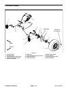
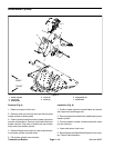
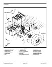
Removal (Fig. 6)
1. Park machine on a level surface, stop engine, set
parking brake and remove key from the ignition switch.
WARNING
Before jackingup themachine, reviewand follow
Jacking Instructions in Chapter 1 -- Safety.
2. Chock wheels not being jacked up. Jack front wheel
off the ground and support machine with appropriate
jack stands.
3. Remove front wheel from machine (see Lower
Steering and Front Wheel Removal in the the Service
and Repairs section of Chapter 5 -- Chassis).
4. Clean hydraulic brake line area of brake caliper to
prevent contamination. Loosen and disconnect brake
line from caliper. Plug brake line and position it away
from caliper.
5. Remove two (2) cap screws and lock washers that
secure the brake caliper to the spindle.
6. Slide brake caliperfrom brakerotor and removecali-
per from machine.
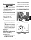
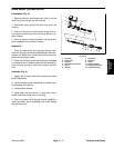
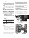
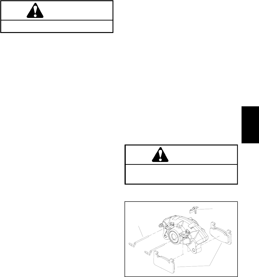
7. If necessary, remove brake pads from caliper (Fig.
7):
A. Remove anti--rattle clip from caliper.
B. Remove pins from caliper by prying with a flat
blade screwdriver through loop in pins.
C. Slide brake pads from caliper. For assembly pur-
poses, note orientation of inner and outer pads as
the pads are not the same.
D. Replace the brake pads if the friction material is
worn to less than 1/32” (0.8 mm).
8. If brake rotor service is necessary, see Lower Steer-
ing andFront Wheelsin the Serviceand Repairssection
of Chapter 5 -- Chassis.
Installation (Fig. 6)
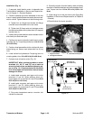
1. If brakepads wereremoved from caliper,install pads
(Fig. 7):
A. If brake pads are being replaced, it will be neces-
saryto pushcaliper pistonsback intothecaliper bore
before installing new pads.
B. Slide brake pads into caliper. Make sure that fric-
tion material on pads is toward brake rotor position.
C. Secure pads into caliper with two (2) pins. Make
sure that pins snap into caliper slots. Install anti--
rattle clip to caliper, pin and brake pads.
2. Slide brake caliper onto brake rotor. Make sure that
rotor is between brake pads.
3. Align caliper mounting holes with spindle. Secure
caliper with two (2) cap screws and lock washers.
4. Install brake hose to caliper.
5. Install front wheel assembly.
6. Lower machinetoground. Torquelug nutsin across-
ing pattern from 45 to 65 ft--lb (61 to 88 N--m).
7. Bleed brakes (see Bleed Brake System in this sec-
tion).
CAUTION
After servicing the brakes, always check the
brakes in a wide open, level area that is free of
other persons and obstructions.
8. Check brake operation.
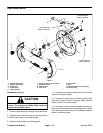
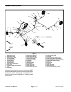
1. Brake pad
2. Pin (2 used)
3. Anti--rattle clip
Figure 7
1
2
3
Transaxle and
Brakes