


Workman MDE
Page 3 -- 24
Electrical System
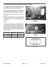
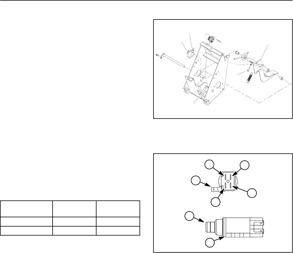
Accelerator Switch
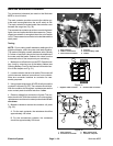
The accelerator switch is a four terminal, two circuit
switch that is located on the control pedal frame (Fig.
37). The Workman MDE uses only one of the switch cir-
cuits (terminals 3 and 4). When the accelerator pedal is
depressed, the switch allows a closed circuit (input) for
the controller to allow traction motor operation. When
theaccelerator pedalis released,the switchprovides an
open circuit (no input) for the controller to prevent trac-
tion motor operation.
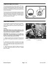
Testing
1. Park vehicle on a level surface, turn on/off switch
OFF and remove key from switch.
2. Locate accelerator switch on pedal frame under
dashboard of vehicle.
3. Unplug wiring harness c onnector from accelerator
switch.
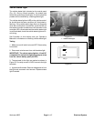
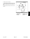
4. With the use of a multimeter (ohms setting), the
switch functions may be tested to determine whether
continuity exists between the switch terminals for both
switch positions.Verify continuity between switchtermi-
nals using the following table:
PLUNGER
POSITION
CONTINUITY
NO
CONTINUITY
IN 1 and 2 3 and 4
OUT 3 and 4 1 and 2
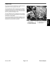
5. When reconnecting wiring harness connector to
switch after testing, harness connector and switch ter-
minal area should be filled with dielectric gel (see Spe-
cial Tools) to prevent corrosion of connection terminals.
Apply gelfully to bothharness connector and switchter-
minalarea,plug harnessconnector intoswitchtodistrib-
ute gel, unplug harness connector, reapply gel to both
surfaces and replug harness connector into s witch.
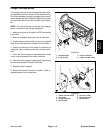
6. If switch replacement is needed, see Accelerator
Switch Adjustment procedure in the Adjustments sec-
tion of this chapter.
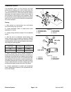
1. Accelerator pedal
2. Accelerator switch
3. Plate
4. Screw (2 used)
5. Stop cap screw
6. Lock nut
Figure 37
1
2
3
4
5
6
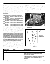
1. Terminal 1
2. Terminal 2
3. Terminal 3
4. Terminal 4
5. Switch plunger
6. Mounting tab
Figure 38
END VIEW
SIDE VIEW
1
2
3
4
6
5
6