


Workman MDE
Page 3 -- 20
Electrical System
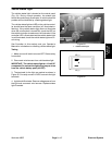
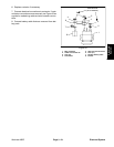
Main and Accessories Contactors
Two contactors (solenoids) are used on the Workman
MDE for circuit control.
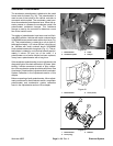
The main contactor provides current to the vehicle con-
troller and is energized when the on/off switch is ON.
The main contactor is located underthe controller cover
beneath the cargo box (Fig. 30).
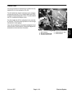
The accessoriescontactor providescurrentto thehead-
lights, horn and optional electrical accessories. The ac-
cessories contactor is energized when the on/off switch
is ON.The accessoriescontactor islocated beneaththe
dash panel.
Testing
NOTE: Prior to taking small resistance readings with a
digital multimeter, short the meter test leads together.
The meter will display a small resistance value (usually
0.5 ohms or less) that isdue to the internal resistance of
the meter and test leads. Subtract this value from the
measured value of the component you are testing.
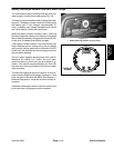
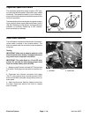
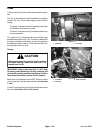
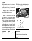
1. Make sureon/off switch is turned OFF.Open the bat-
tery circuit by removing one of the battery cables (see
Opening Battery Circuit in the General Information sec-
tion of this chapter and Fig. 31).
2. Locate contactor that is to be tested. Disconnect all
vehicle harness electrical connections from contactor.
Note wire connector locations on contactor for reas-
sembly purposes.
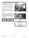
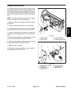
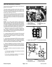
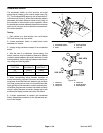
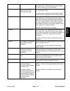
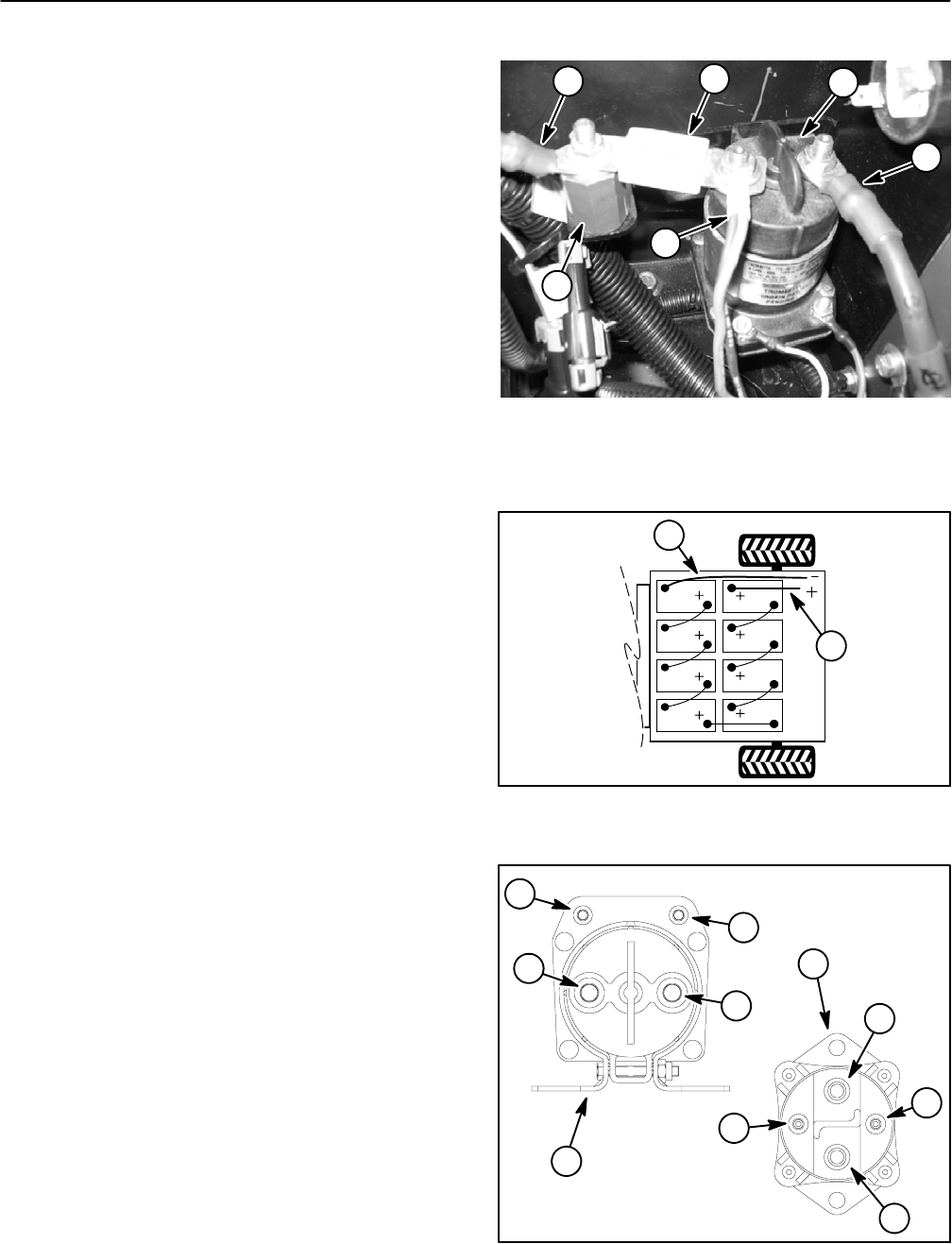
3. Usingjumper wires,apply48 VDCdirectly acrossthe
contactorcoil posts(Fig.32).The contactorshouldclick.
With the contactor coil energized, resistance across the
main contact posts should be less than 1 ohm.
4. Remove voltage from contactor coil posts. The con-
tactorshould click.Withthe contactorcoil notenergized,
resistance across themain contactposts shouldbe infi-
nite ohms.
5. Measure resistance across the contactor coil posts
(Fig. 32):
A. For the main contactor, the resistance should be
approximately 126 ohms.
B. For the accessories contactor, the resistance
should be approximately 200 ohms.
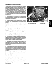
1. Main contactor
2. Cable to controller B+
3. Wire harness connector
4. Fuse (F1)
5. Positive battery cable
6. Isolator
Figure 30
1
2
3
6
5
4
1. Negative cable to vehicle 2. Positive cable to vehicle
Figure 31
A
4
1
2
Figure 32
1. Main contactor
2. Accessories contactor
3. Main contact posts
4. Contactor coil posts
1
2
3
3
3
3
4
4
4
4