


Workman MDE Transaxle and BrakesPage 4 -- 11
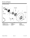
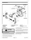
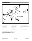
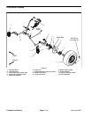
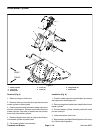
Inspection (Fig. 4)
1. Inspect brake drums.
IMPORTANT:Brake drum machining is not re-
commended. Replace brake drums as a set to
maintain equal braking forces.
A. Clean drums with denatured alcohol. Check
braking surface diameter in at least three places. If
the diameter exceeds 6.320” (160.5 mm), replace
both brake drums.
B. Replacedrums thatarecracked,deeplygrooved,
tapered, significantly out--of --round, scored, heat
spotted or excessively rusted.
C. Minor scoring can be removed with sandpaper.
2. Inspect brake shoe linings.
IMPORTANT:Replace brake shoes as a set (all
four shoes) to maintain equal braking forces.
A. Replace brake shoes if damaged or if lining is
worn to 1/16” (1.6 mm). Replace if lining is contami-
nated by oil, grease, or other fluids.
NOTE: Overheated springs lose their tension, and
can cause brake linings to wear out prematurely.
B. Inspect brake shoe webbing, upper and lower
springs, and shoe hold down springs for overheat-
ing.Overheatingis indicatedbya slightbluecolor.In-
spect brake shoe webbing for deformation. Replace
parts as necessary.
C. Inspect hold down pins on adjuster levers for
bends, rust and corrosion. Replace as necessary.
3. Inspect backing plate surfaces, which contact with
the brake shoes for grooves that may restrict shoe
movement. Replace plate if grooves can not be re-
moved by light sanding with emery cloth or other suit-
able abrasive. Replace plate if cracked, warped or
excessively rusted.
4. Inspect adjusterlevers fordeformation. Replacelev-
ers if deformation or excessive rust is found.
5. Replace parking brake cables if frayed, stretched or
kinked.
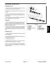
Assembly (Fig. 4)
IMPORTANT:Brake shoe lining surfaces must be
free of grease, oil and other foreign matter.
1. Apply a light film of lubricant to the following:
A. Ledges on which the brake shoes rest.
B. Pin surfaces on adjuster levers.
C. Anchor block surface that contacts shoe webs.
D. Both surfaces of belleville washers that are posi-
tioned between adjuster levers and backing plate.
2. If removed, position lubricated belleville washer be-
tween leveradjuster and backingplate. Secureadjuster
to backing plate with washer and bolt. Torque bolt from
110 to 120 in--lb (12.4 to 13.6 N--m).
3. If removed, secure wheel cylinder to backing plate
with two (2) washer head screws. Torque screws from
110 to 120 in--lb (12.4 to 13.6 N--m).
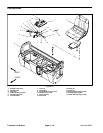
4. Ifremoved frombackingplate, slideparkingbrake le-
ver into slot and dust cover in backing plate.
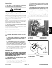
5. Position brake shoes to backing plate. Make sure
that each shoe is properly positioned at anchor block,
parking brake lever, wheel cylinder and pin on adjuster
lever. Secure shoes to backing plate with shoe hold
down cups and springs.
CAUTION
Be careful when installing springs to brake
shoes. The springs are under heavy load and
may cause personal injury.
6. Secure brake shoes with upper and lower s prings.
Transaxle and
Brakes