


Workman MDE
Transaxle and Brakes
Page 4 -- 22
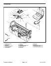
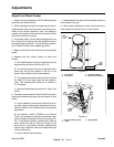
Installation (Fig. 11)
1. If removed, install traction motor to transaxle (see
Traction Motor Installation in Service and Repairs sec-
tion of Chapter 3 -- Electrical System).
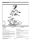
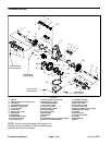
2. Position transaxle and motor assembly to the rear
frame. Looselyinstall allfasteners used to secure trans-
axle to vehicle. Tighten fasteners in the following order:
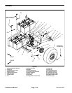
A. Tighten four (4) flange head screws and flange
nuts that secure transaxle to the rear frame.
B. Tighten two (2) flange nuts and carriage screws
that secure transaxle mountplate (item 5) to support
bracket (item 4).
3. Install parking brake cables to brake actuator levers
with clevis pins and cotter pins.
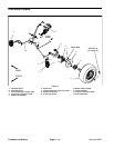
4. Position and secure hydraulic brake lines to wheel
cylinders (Fig. 3). Torque banjobolts from 15 to 21 ft--lb
(21to28N--m).
5. Position wheel assemblies to the vehicle with v alve
stems facing out. Secure each wheel with five (5) lug
nuts.
6. Lower vehicle from jackstands. Torque lug nuts in a
crossing pattern from 45 to 65 ft--lb (61 to 88 N--m).
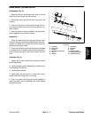
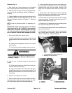
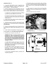
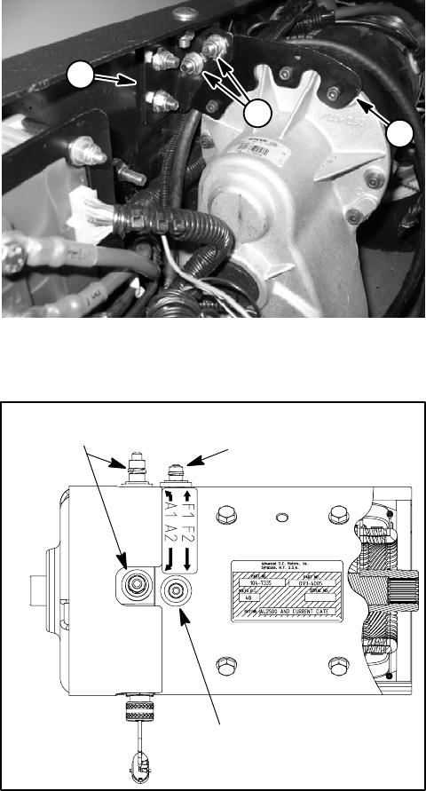
7. Connect wires to traction motor (Fig. 15):
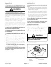
IMPORTANT: W hen connecting cables to motor
terminals (A1, A2, F1 and F2), use a back--up
wrench to retain lower nut before tightening up-
per nut (Fig. 12). If terminal studs are allowed to
turn during upper nutinstallation, internal motor
damage can occur.
A. Install cable connector and upper nut to motor
terminals A1 and A2. While retaining lower nut,
torque upper nut on terminals A1 and A2 from 85 to
90 in--lb (9.6 to 10.2 N--m).
B. Install cable connector and upper nut to motor
terminals F1 and F2. While retaining lower nut,
torque upper nut on terminals F1 and F2 from 55 to
60 in--lb (6.2 to 6.8 N--m).
C. Plug motor temperature sensor connector into
vehicle wire harness.
8. Carefully connect removed battery cable to battery
terminals.Installlock washersand nutsonbattery termi-
nals. Torque nuts from 115 to 125 in--lb (13.0 to 14.1
N--m).
9. Install cargo box to the rear frame (see Cargo Box
Installation in Service and Repairs section of Chapter 5
-- Chassis).
10.Check brakes for proper operation.
1. Support bracket
2. Carriage screws/nuts
3. Transaxle mount plate
Figure 14
2
3
1
Figure 15
55 to 60 in--lb
(6.2 to 6.8 N--m)
85 to 90 in--lb
(9.6 to 10.2 N--m)
55 to 60 in--lb
(6.2 to 6.8 N--m)