


Workman MDE Transaxle and BrakesPage 4 -- 21
Removal (Fig. 11)
1. Park vehicle on a level surface, turn on/off switch
OFF, set parking brake and remove key from switch.
2. Remove cargo box from vehicle(see Cargo Box Re-
moval in Service and Repairs section of Chapter 5 --
Chassis).
3. Open the battery circuit by carefully removing one of
the battery cables (see Opening Battery Circuit in the
General Information section of Chapter 3 -- Electrical
System).
NOTE: Label all electrical leads for assembly pur-
poses.
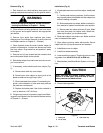
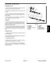
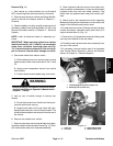
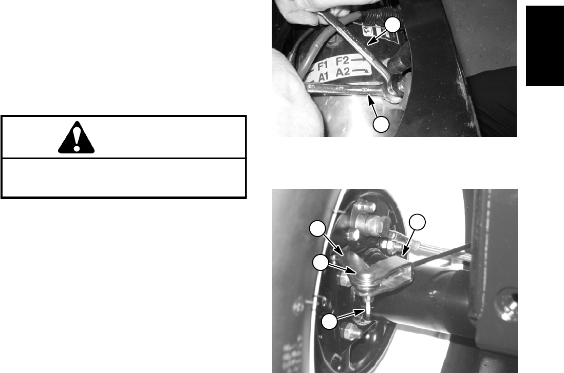
IMPORTANT: When removing cables from traction
motor terminals(A1, A2, F1 and F2),use a wrenchto
retain lower nut before loosening upper nut (Fig.
12). If terminal studs are allowed to turn during up-
per nut removal, internal motor damage can occur.
4. Disconnect cables from traction motor:
A. While retaining lower nut, remove upper nut and
cable connectorfrom motor terminalsA1, A2,F1 and
F2.
B. Unplug motor temperature sensor from vehicle
wire harness.
C. Position disconnected cables away from motor.
WARNING
Before jacking up the vehicle, review and follow
Jacking Instructionsin Operator’sManual and in
Chapter 1 -- Safety.
5. Jack up rear of vehicle enough to remove rear
wheels.
A. Chock the front and rear of both front tires to pre-
vent the vehicle from moving.
B. Support both sides of the rear frame with jack-
stands positioned just in front of the axle tubes. This
willallow thetransaxle tobe removedfromthe rearof
the vehicle.
6. Remove rear wheels from vehicle.
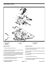
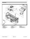
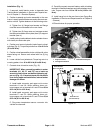
7. Remove cotter pins andclevis pins thatsecure park-
ing brake cablesto brakeactuator levers (Fig.13). Posi-
tion brake cables away from transaxle assembly.
8. Clean hydraulic brake line area of rear brake cylin-
ders to prevent contamination. Loosen and disconnect
hydraulic brake line from both wheel cylinders. Plug
brake lines and position them away from wheel cylin-
ders.
9. Attach hoist to the transaxle and motor assembly.
Make sure liftingdevice is attached soit can holdthe full
weight of the transaxle and traction motor.
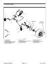
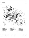
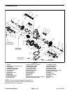
10.Loosen and remove two (2) flange nuts andcarriage
screws that secure transaxle mount plate (item 5) to
support bracket (item 4) (Fig. 14).
11.Remove four (4)flange head screwsand flange nuts
securing the transaxle to the rear frame.
12.Carefully lower transaxle and motor assembly from
the rear of the vehicle.
13.If necessary, remove traction motor from transaxle
(see Traction Motor Removal in Service and Repairs
section of Chapter 3 -- Electrical System).
1. Loosening/tightening wrench (upper nut)
2. Retaining wrench (lower nut)
Figure 12
2
1
1. Cotter pin
2. Clevis pin
3. Brake cable bracket
4. Brake actuator lever
Figure 13
2
3
1
4
Transaxle and
Brakes