Rev. A
Workman MDE
Page 3 -- 25
Electrical System
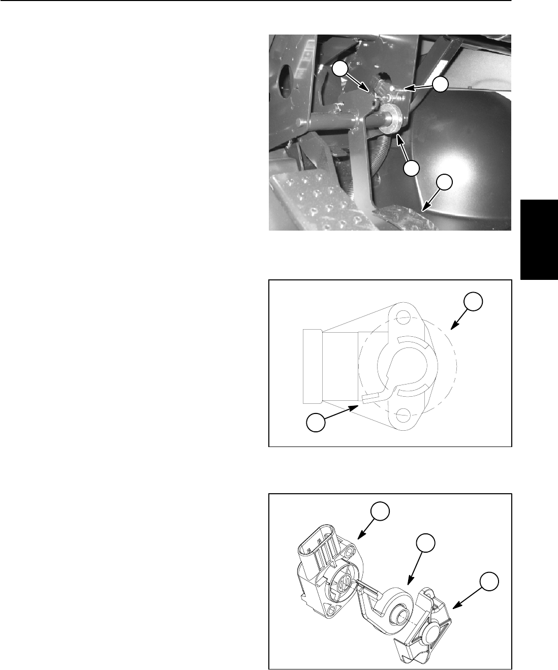
Accelerator Potentiometer
The accelerator potentiometer is attached to the pedal
frame under the dash (Fig. 39). This potentiometer is
used as one of the inputs for the vehicle controller to
command vehicle speed. The accelerator pedal posi-
tions the accelerator potentiometer lever. When the op-
erator presses or releases the accelerator pedal, the
potentiometer resistance changes. This resistance
change is used by the controller to determine current
flow to the traction motor.
Two styles of potentiometer have been used on Work-
man MDE vehicles. Vehicles with serial numbers below
310000000 havea potentiometerwith ashort lever (Fig.
40). This potentiometer is rotated by a roll pin that ex-
tends approximately1 1/2inches (38 mm)out ofthe col-
lar. Vehicles with serial numbers above 310000000
have apotentiometer witha longlever (Fig.41). Thispo-
tentiometer is rotated by a roll pin that extends approxi-
mately 3 inches (76 mm) out of the collar. If a
potentiometer on an earlier vehicle has been replaced,
it may have a potentiometer with a long lever.
If theaccelerator potentiometer is outof adjustment, the
diagnostic light on the dash will flash six (6) times. Addi-
tionally, if vehicle movement is erratic or jerky, calibra-
tion ofthe acceleratorsystem shouldbe performed.See
Accelerator Potentiometer Adjustment and Accelerator
System Calibration in the Adjustments section of this
chapter.
Before suspecting a faulty potentiometer, follow adjust-
ment procedures for the accelerator switch, accelerator
potentiometer and acceleration system calibration
found in the Adjustments section of this chapter.
1
2
3
4
1. Potentiometer
2. Accelerator pedal
3. Collar
4. Roll pin
Figure 39
1. Potentiometer 2. Lever (short)
Figure 40
2
1
Figure 41
1. Potentiometer
2. Lever (long)
3. Retainer
2
1
3
Electrical
System


