


Appendix B: Port Pinouts
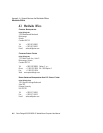
DB-26 Auxiliary Port Pinout
B-2 Psion Teklogix 8525 G2/8530 G2 Vehicle-Mount Computer User Manual
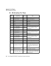
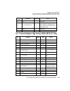
B.3 DB-26 Auxiliary Port Pinout
Pin
Number
Signal Name Signal Type Notes
1 EXT_5V_SW Power 5 VDC @ 0.5 A maximum.
2 EXT_5V_SW Power 5 VDC (Tied to pin 1).
3N/C Not used.
4N/C Not used.
5N/C Not used.
6N/C Not used.
7GND Power
8 P1_USB_HOST+ 5V diff 12 Mbps serial data interface; con-
nects as a USB host to a USB
client device.
9 P1_USB_HOST- 5V diff
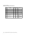
10 GND Power
11 USB_DEVICE+ 5V diff 12 Mbps serial data interface; con-
nects as a USB client to a USB
host device.
12 USB_DEVICE- 5V diff
13 GND Power
14 P2_USB_HOST+ 5V diff 12 Mbps serial data interface; con-
nects as a USB host to a USB
client device.
15 P2_USB_HOST- 5V diff
16 GND Power
17 CONSOLE_RXD RS232D Console / diagnostic port.
18 CONSOLE_TXD RS232D Console / diagnostic port.
19 GND Power
20 CONSOLE_TXD_SEL 3V3
Grounding this pin selects the
PCON as the console data source;
disconnecting it selects the main
processor.
21 MOTION DETECT 3V3
Grounding this pin indicates that
the terminal is in motion.
22 AUXILARY_PORT_ID Analog
Connect this pin to ground through
an external resistor to identify the
connected device.