


Chapter 6: Peripheral Devices & Accessories
Wiring Vehicle Power To The 8525 G2/8530 G2
180 Psion Teklogix 8525 G2/8530 G2 Vehicle-Mount Computer User Manual
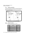
6.3.8 Wiring Vehicle Power To The 8525 G2/8530 G2
Warning: The 8525 G2/8530 G2 accepts DC power sources between 10V
and 90VDC nominal.
Applying a voltage above 90VDC or reversing polarity may
result in permanent
damage to the 8525 G2/8530 G2 and will void
the product warranty.
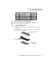
A 1.8 meter (6 ft.) extension power cable (PN 13985-302 std or –301 display off) is
supplied with your 8525 G2/8530 G2. This cable should be wired to a filtered, fused
(maximum 10A) accessory supply on the vehicle. The 8525 G2/8530 G2 draws no
more than 8A (less if the accessory supply is greater than 12V). Any additional
wiring (minimum 18 gauge), connectors or disconnects used should be rated for at
least 90 VDC, 10A.
When connecting PN 13985-301 (display-off version), ensure that the screen
blanking wires (clearly labelled) and the power wires (red/black leads) are reliably
secured away from each other, or are separated with reliably secured certified
insulation. Minimum 2.8mm distance, or 0.4mm distance through insulation is
required for the separation.
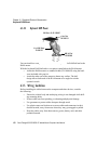
The red lead of the power cable attaches to the positive vehicle supply. The black
lead connects to the negative supply – this should be connected to a proper terminal
block and not to the vehicle body. The 8525 G2/8530 G2 is fully isolated and can be
used with both negative and positive chassis vehicles.
You may have the option of connecting power before or after the ‘key’ switch.
It is preferable to wire the 8525 G2/8530 G2 after the key switch – that is, the
8525 G2/8530 G2 cannot be switched on without turning the vehicle key on.
However, if the operator switches the key off repeatedly for long periods during a
shift, it may make more sense to wire the 8525 G2/8530 G2 before the switch.
Keep in mind that the 8525 G2/8530 G2 will continue to operate with or without
vehicle power as long as its back up battery has sufficient charge.
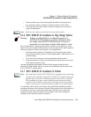
If an unfused power source must be used, a fuse assembly (PN 19440) must be
added to the extension power cable (the fuse and instructions are supplied with the
cable). Use only a 10A slow blow UL approved fuse in the fuse assembly. The fuse
assembly must be located as close as practical to the DC supply, and shall connect to
the positive side of the DC supply.