


Psion Teklogix 8525 G2/8530 G2 Vehicle-Mount Computer User Manual B-1
APPENDIX B
PORT P INOUTS
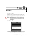
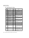
B.1 Tether Port Pinout
The tether port connector incorporates multiplexed undecoded scanner, decoded
scanner, RS232 serial, and USB interfaces. In order for it to operate, a special wiring
scheme is needed. If you need to create cables for the tether port, contact Psion
Teklogix and request an instruction sheet for tether port termination.
Important: Do not attempt to interface with the tether connector without
direction from a qualified Psion Teklogix technician. Doing
so may cause damage to the 8525 G2/8530 G2 and/or the
tethered device.
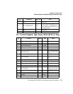
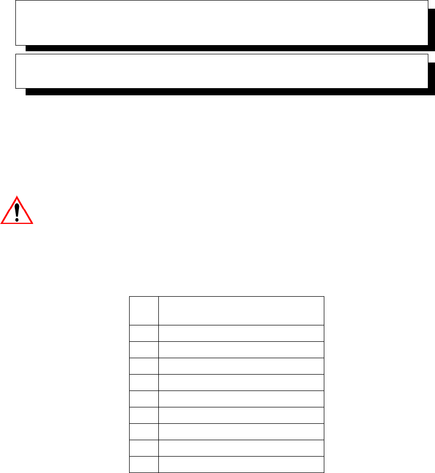
B.2 RS232 Port Pinout
* CAUTION: If enabled (software configurable), 5V or 12V power will appear on this line,
which may be the Ring Indicator line on some devices such as modems.
1/2 Amp Max.
Pin
No.
Description
1 DCD (Data Carrier Detect)
2 RXD (Receive Data)
3 TXD (Transmit Data)
4 DTR (Data Terminal Ready)
5 GND (Signal Ground)
6 DSR (Data Set Ready)
7 RTS (Ready To Send)
8 CTS (Clear to Send)
* 95V POWER *