


2-26
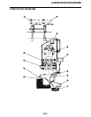
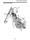
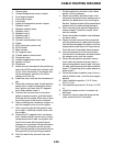
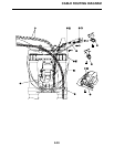
CABLE ROUTING DIAGRAM
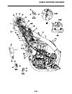
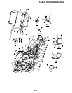
1. Clutch cable
2. Throttle cable (return)
3. Throttle cable (pull)
4. Cable holder
5. Clamp
6. Rectifier/regulator
7. Ignition coil
8. Ignition coil coupler
9. AC magneto coupler
10. Radiator hose 2
11. Ground lead terminal
12. Plug cap
13. Ignition coil bracket
14. Clamp (lock)
15. Clamp (clip)
16. AC magneto lead
17. ECU bracket
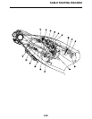
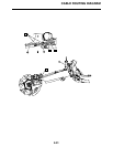
A. Pass the clutch cable, throttle cables, and
engine stop switch lead through the cable
holder. Pass the clutch cable through the
lower guide only.
B. Route the engine stop switch lead to the in-
side of the clip.
C. Fasten the rectifier/regulator lead and en-
gine stop switch lead (wire harness end).
D. Insert the projection on the engine stop
switch coupler into the hole in the bracket.
E. Insert the projection on the rectifier/regula-
tor coupler into the hole in the bracket.
F. Position the ignition coil bracket to the out-
side of the ignition coil, and insert the bolts
from the ignition coil side.
G. Fasten the AC magneto lead to the ignition
coil bracket with a plastic locking tie, mak-
ing sure to position the tie above the lower
mounting portion of the bracket. Face the
buckle of the plastic locking tie forward,
and then cut off the excess end of the tie.
H. Route the ignition coil lead between the
condenser and the ignition coil.
I. Fit the clip portion of the clamp into the ig-
nition coil bracket and fasten the clutch ca-
ble with the locking portion of the clamp.
J. Route the clutch cable to the outside of the
AC magneto lead.
K. Route the throttle cables under radiator
hose 2, making sure not to twist the cables.
L. Route the AC magneto lead to the inside of
the throttle cables and clutch cable.
M. Install the ground lead terminal between
the ECU bracket and the cable holder,
making sure to position the terminal be-
tween the stoppers.
N. Push in the spark plug cap completely,
making sure that there is no gap between
the cylinder head cover and the cap.
O. Apply sealant to the slit and inner surface
of the grommet, and then install the grom-
met at the position shown.