5-41
HANDLEBAR
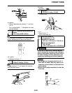
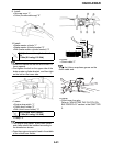
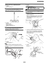
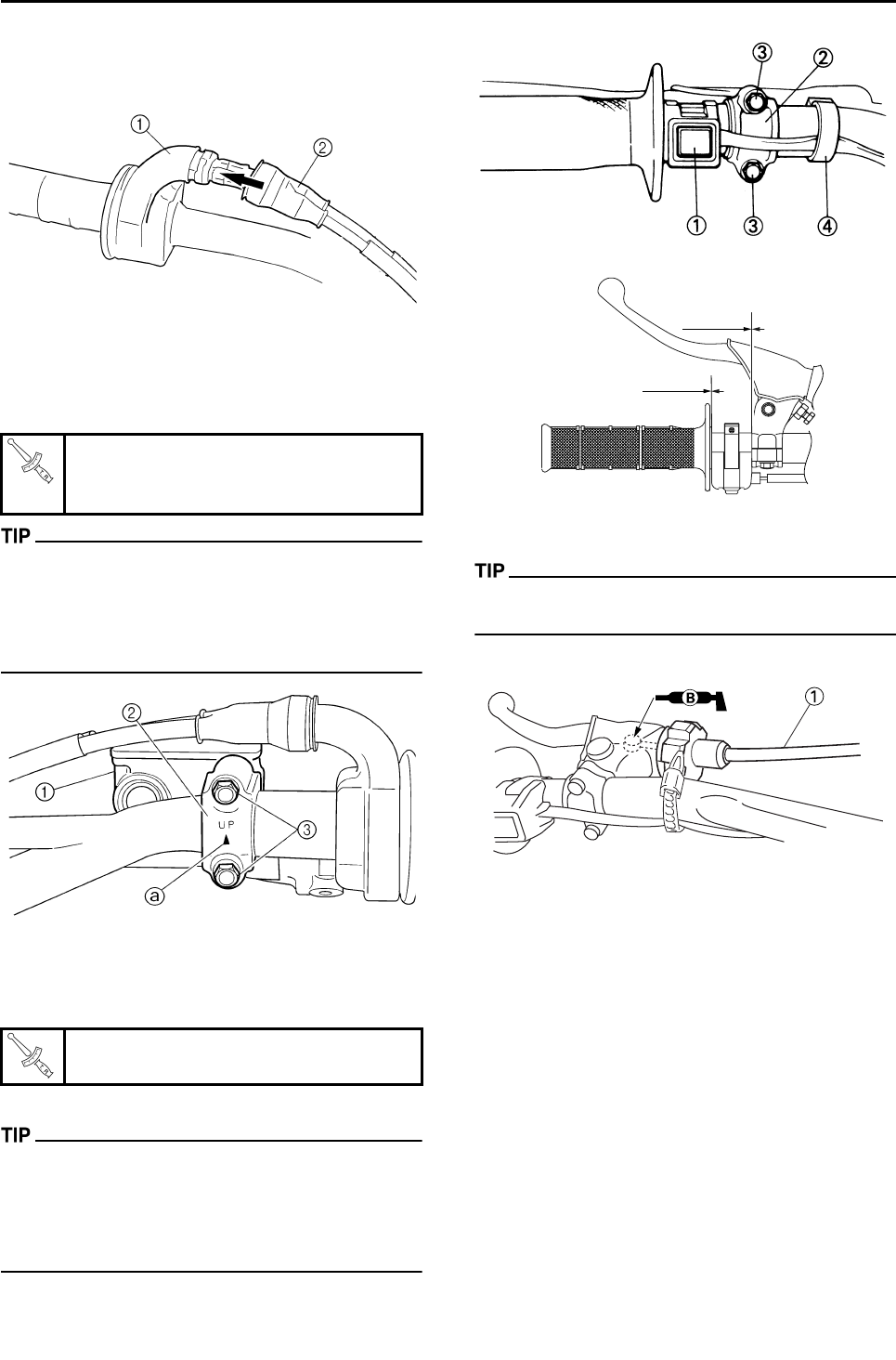
9. Install:
• Grip cap cover "1"
• Cover (throttle cable cap) "2"
10.Install:
• Brake master cylinder "1"
• Brake master cylinder bracket "2"
• Bolt (brake master cylinder bracket) "3"
• Install the bracket so that the arrow mark "a"
faces upward.
• First tighten the bolt on the upper side of the
brake master cylinder bracket, and then tight-
en the bolt on the lower side.
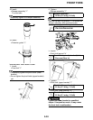
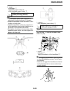
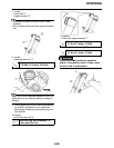
11.Install:
• Engine stop switch "1"
• Clutch lever holder "2"
• Bolt (clutch lever holder) "3"
•Clamp "4"
• The engine stop switch, clutch lever holder
and clamp should be installed according to
the dimensions shown.
• Pass the engine stop switch lead in the middle
of the clutch lever holder.
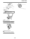
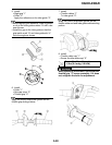
12.Install:
• Clutch cable "1"
Apply the lithium soap base grease on the
clutch cable end.
13.Adjust:
• Clutch lever free play
Refer to "ADJUSTING THE CLUTCH CA-
BLE FREE PLAY" section in the CHAPTER
3.
Bolt (brake master cylinder brack-
et):
9 Nm (0.9 m•kg, 6.5 ft•lb)
Bolt (clutch lever holder):
5 Nm (0.5 m•kg, 3.6 ft•lb)
0 mm
0 mm


