5B.23
Section 5B
EFI Fuel System
5B
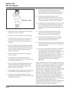
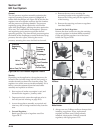
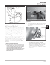
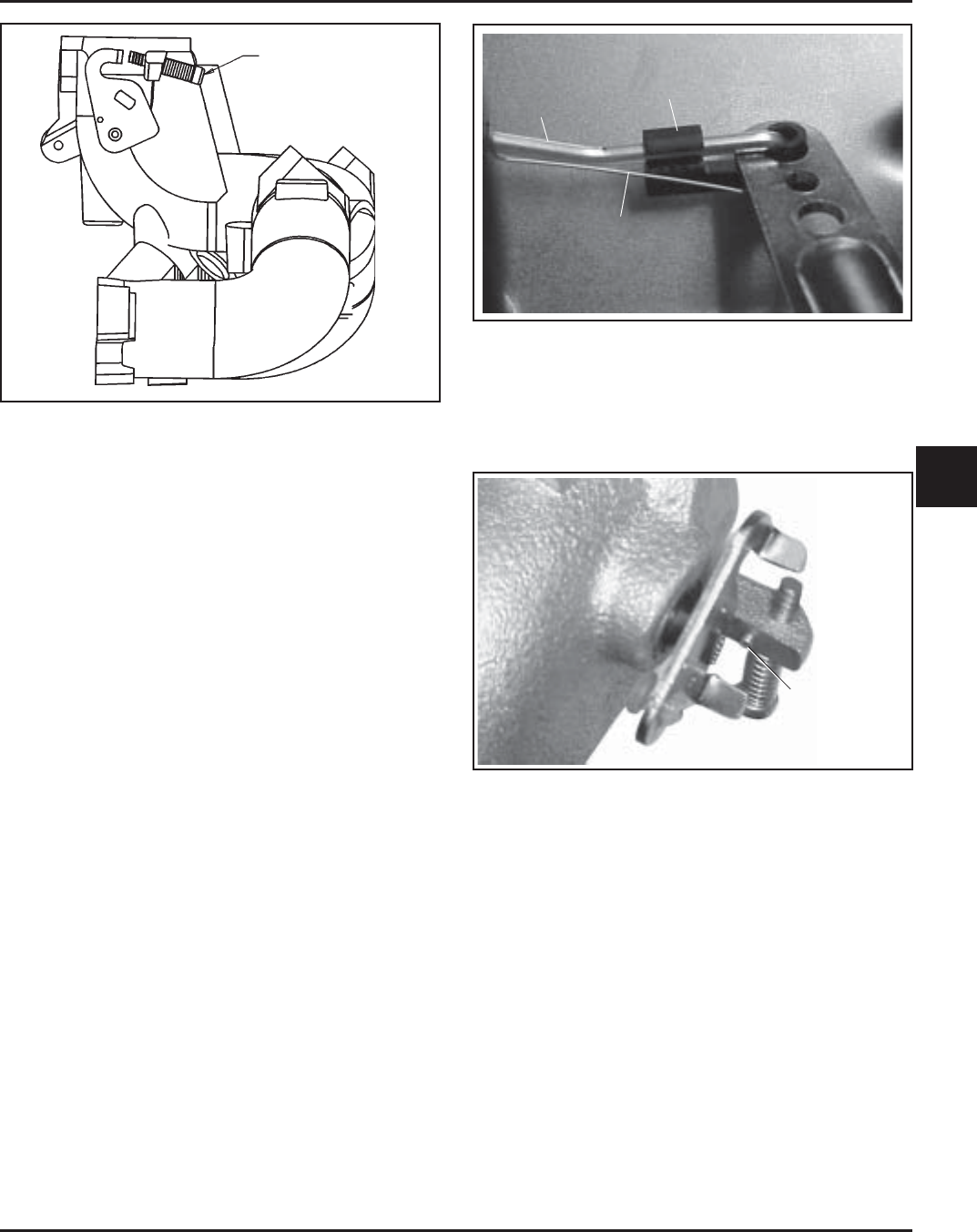
Figure 5B-33. Idle Speed Screw Details.
Initial Governor Adjustment
The initial governor adjustment is especially critical
on EFI engines because of the accuracy and sensitivity
of the electronic control system. Incorrect adjustment
can result in overspeed, loss of power, lack of
response, or inadequate load compensation. If you
encounter any of these symptoms and suspect them to
be related to the governor setting, the following
should be used to check and/or adjust the governor
and throttle linkage.
If the governor/throttle components are all intact, but
you think there may be a problem with the
adjustment, follow Procedure A to check the setting. If
the governor lever was loosened or removed, go
immediately to Procedure B to perform the initial
adjustment.
A. Checking the Initial Adjustment
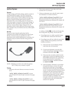
1. Unsnap the plastic linkage bushing attaching the
throttle linkage to the governor lever. See Figure
5B-34. Unhook the damper spring from the lever,
separate the linkage from the bushing, and
remove the bushing from the lever. Mark the hole
position and unhook the governor spring from
the governor lever.
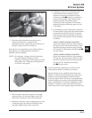
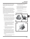
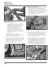
Figure 5B-35. Throttle Details.
a. On engines with a stop screw, pivot the
throttle shaft and plate into the “Full Throttle”
position, so the tang of the throttle shaft plate
is against the end of the high-speed stop
screw. See Figure 5B-35. Temporarily clamp in
this position.
Idle Speed
Screw
Figure 5B-34. Throttle Linkage/Governor Lever
Connection.
2. Check if the engine has a high-speed throttle stop
screw installed in the manifold casting boss. See
Figure 5B-35.
High-Speed
Throttle Stop
Screw
Linkage
Bushing
Throttle
Linkage
Damper
Spring


