5.18
Section 5
Fuel System and Governor
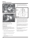
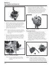
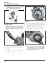
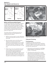
2. Remove the three screws securing the cover to the
accelerator pump housing. Remove the cover,
spring, and diaphragm. See Figure 5-30.
Figure 5-30. Accelerator Pump Cover and
Diaphragm Removed.
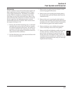
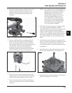
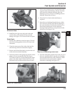
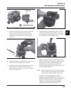
3. Remove the retaining ring over the rubber check
valve, using a snap ring pliers. Remove the check
valve from the fuel delivery chamber. See Figure
5-31.
Figure 5-31. Removing Retaining Ring.
4. Clean the accelerator pump housing and cover as
required.
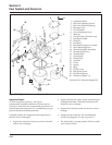
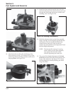
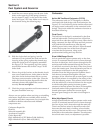
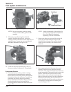
5. Install the new check valve into the fuel delivery
chamber. Secure with the new retaining ring. See
Figure 5-32.
Figure 5-32. Check Valve and Retaining Ring
Installed.
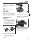
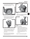
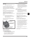
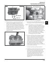
6. Notice the small alignment tab and the small
bead on one side of the outer diameter of the new
diaphragm. Install the diaphragm into the
housing, so the alignment tab is in the small
notch, the bead is down in the recessed channel,
and the “donut” around the metal center plate
should be out, facing you. See Figure 5-33.
Figure 5-33. Diaphragm Installed.
7. Install the new diaphragm spring and reinstall
the accelerator pump cover. Secure with the three
new screws. Torque the screws to 2.0 ± 0.6 N·m
(18.2 ± 5.2 in. lb.). See Figure 5-34.


