10.14
Section 10
Inspection and Reconditioning
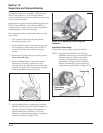
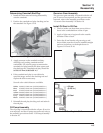
5. After torquing, rotate the gear and check for
freedom of movement. Make sure there is no
binding. If binding occurs, loosen the screws,
reposition the pump, retorque the hex flange
screws and recheck the movement.
Crankcase Breather System
The breather system is designed to control the amount
of oil in the head area and still maintain the necessary
vacuum in the crankcase.
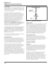
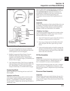
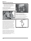
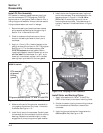
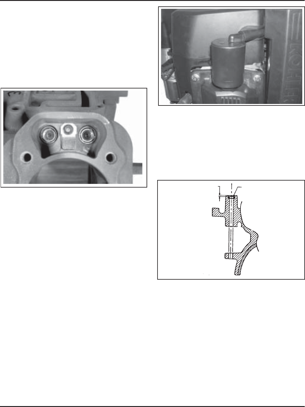
Figure 10-20. Oil Separator.
Governor Cross Shaft Oil Seal
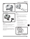
If the governor cross shaft seal is damaged and/or
leaks, replace it using the following procedure.
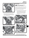
Remove the oil seal from the crankcase and replace it
with a new one. Install the new seal to the depth
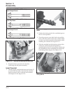
shown in Figure 10-21 using a seal installer.
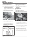
Figure 10-19. Crankcase with Breather Reed.
A spring steel reed and stop is mounted on each bank
of the crankcase, between the lifter bores. See Figure
10-19. When the pistons move downward, air is
pushed past the reeds into the cylinder head cavities.
On the #2 cylinder, the upper end of the head is
completely sealed by the rocker cover, so a low,
positive pressure is created in the head cavity. The #1
rocker cover has a hole in it for venting. The bottom
nipple of an oil separator canister is fitted into the
hole with a grommet. From the top nipple of the
canister, a breather hose goes back to the air cleaner
base. The air moving into the #1 head cavity is filtered
through the oil separator and then is drawn into the
air intake. See Figure 10-20.
The upward travel of the pistons closes the reeds and
creates a low vacuum in the lower crankcase. The
combination of low pressure above and low vacuum
below forces any accumulated oil out of the #2 head
area into the crankcase. On the #1 bank you have
atmospheric pressure above and vacuum below, again
drawing any oil toward the crankcase.
2.0 mm (0.0787 in.)
Governor Cross
Shaft Seal
Figure 10-21. Installing Cross Shaft Oil Seal.


