


5.5
Section 5
Fuel System and Governor
5
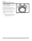
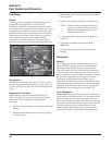
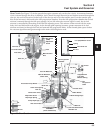
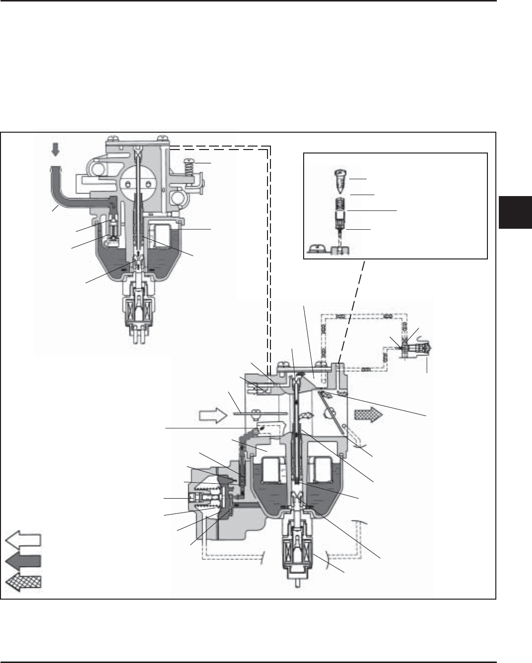
Figure 5-3. Slow Circuit.
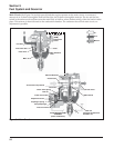
Fuel Inlet
Float Valve Seat
Float Valve
Main Jet
Float
Main Emulsion
Hole
Idle Speed
(RPM)
Adjustment
Screw
Air
Fuel
Mixture
Check Valve Spring
Outlet Check Valve
Leak Jet
Adjustment Screw
Diaphragm Spring
Pump Diaphragm
Inlet Check Valve
ACCELERATOR PUMP
ASSEMBLY
(Some Carburetors)
Fuel Shut-Off Solenoid
with Main Jet
Main Jet
Slow Passage Pipe
Main Nozzle
Throttle Valve
Idle
Progression
Holes
Idle Limiter
Jet
Capped/Preset
Low (Idle)
Mixture Setting
Idle Port
Idle Progression
Chamber
Slow
Jet
Slow Air Bleed Jet
Choke Valve
Main Air Bleed Jet
Accelerator Pump Nozzle
Bowl Vent
Slow Circuit: (See Figure 5-3) At low speeds the engine operates only on the slow circuit. As a metered amount
of air is drawn through the slow air bleed jet, fuel is drawn through the main jet and further metered through the
slow jet. Air and fuel are mixed in the body of the slow jet and exit to the transfer port. From the transfer port
this air fuel mixture is delivered to the idle progression chamber. From the idle progression chamber the air fuel
mixture is metered through the idle port passage. At low idle when the vacuum signal is weak, the air fuel
mixture is controlled by the setting of the idle fuel adjusting screw. This mixture is then mixed with the main
body of air and delivered to the engine. As the throttle plate opening increases, greater amounts of air fuel
mixture are drawn in through the fixed and metered idle progression holes. As the throttle plate opens further
the vacuum signal becomes great enough so the main circuit begins to work.
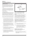
Low (Idle) Mixture Screw
Keihin Carburetors Only
Idle Limiter Jet
Idle Port
Spring