


Installation Information
This section of the Appendix provides information on connecting the
GPSMAP 276C to auxiliary devices and removing the antenna.
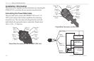
Connecting the Power/Data Cable
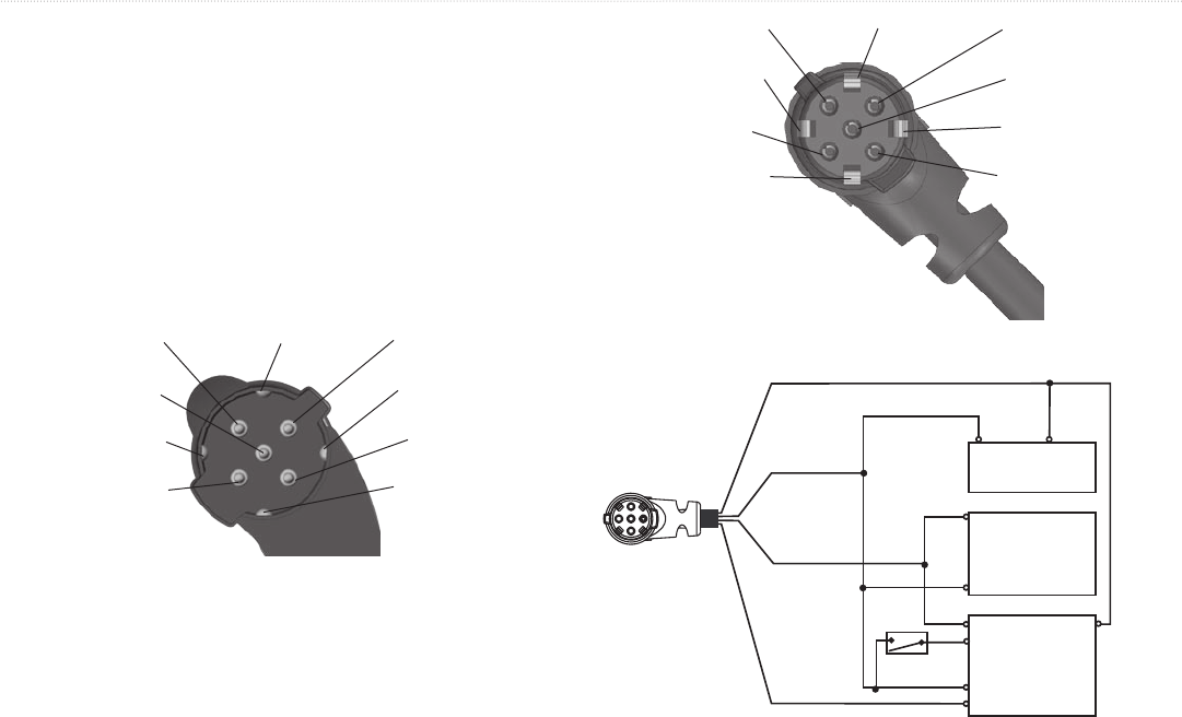
The power/data cable connects the GPSMAP 276C to an 11–35
VDC system and provides interface capabilities for connecting
external devices. The color code in the diagram below and to the
right indicates the appropriate harness connections. Replacement
fuse is a 3AG - 1.5 Amp fuse.
Power/Data Connector on the GPSMAP 276C Unit
Data Out 1
Blue
Ground
Black
Voice (-)
Orange
Data In
2 Green
Alarm
White
Power
Red
Voice (+)
Brown
Data In
1 Yellow
Data Out 2
Violet
Power/Data Connector on the Cable
Data Out 1
Blue
Ground
Black
Voice (-)
Orange
Data In
2 Green
Alarm
White
Power
Red
Voice (+)
Brown
Data In
1 Yellow
Data Out 2
Violet
Yellow:
Data In 1
Black:
Ground
Red: Power
11–35 VDC
(-) (+)
Autopilot/
NMEA Device
RXD +
RXD -
GSD 20
Sounder
(-)
(+)
White/Blue
White/Brown
Blue:
Data Out 1
Orange
Closed - On,
Open - Off
Switch
104 GPSMAP 276C Owner’s Manual
APPENDIX > INSTALLATION INFORMATION