


2--33
62--11362
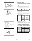
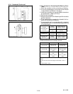
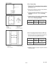
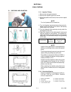
2.3.5 Cylinder
a. Top
b. Middle
c. Bottom (skirt)
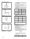
a. Right--angled to
Piston Pin
b. Piston Pin Direction
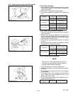
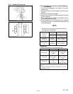
1. Cylinder I.D.
(before correction)
2. Oversize C ylinder I.D.
2.3.5.a Cylinder Wear
1. Measure the I.D. of the cylinder at the six positions
(see figure with a cylinder gauge to find the maximum
and minimum I.D.’s.
2. Determine the d if ference (maximum wear) between
the maximum and minimum I.D.’s.
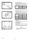
3. If the wear exceeds the allowable limit, bore andhone
to the oversize dimension. (refer to Correcting
Cylinder)
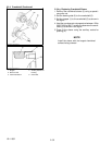
4. V isually c heck the cylinder wall for s cratches. If deep
scratches are found, the cylinder walls should b e
bored. (refer to Correcting Cylinder)
Cylinder I.D.
Factory
Specification
83.000 to 83. 022 mm
3.2678 to 3. 2685 in.
Maximum Wear
Allowable
Limit
83.170 mm
3.2744 in.
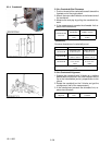
2.3.5.b Correcting Cylinder (Oversize +0.25 mm)
1. When the cylinder is worn beyond the allowable limit,
bore and hone it to the specified dimension.
Cylinder I.D.
Factory
Specification
83.250 to 83. 272 mm
3.2776 to 3. 2784 in.
Maximum Wear
Allowable
Limit
83.420 mm
3.2843 in.
Finishing
Hone to 2.2 t o 3.0 mm μRmax.
(0.00087 to 0.001 18 in. μRmax.)
2. Replace the piston and piston rings with o versize
(+0.25 mm) ones.