


2--22
62--11362
2.3.1 Cylinder Head And Valves (Continued)
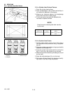
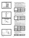
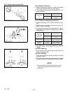
2.3.1.i Free Length and Tilt of Valve Spring
1. Measure thefreelengthA ofthevalvespring withver-
nier calipers. If the measurement is less than the al-
lowable limit, replace the spring.
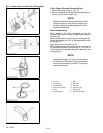
2. Put the valve spring on a surface plate, place a
square on the side of the valve spring.
3. Check to see if the entire side is in contact with the
square. Rotate the spring andmeasure for maximum
tilt B. Check the entire s urface of the valve spring for
defects. If any are found, replace it.
Free Length A
Factory
Specification
41.7 to 42. 2 mm
1.65 to 1. 66 in.
Allowable Limit
41.2 mm
1.62 in.
Tilt B Allowable Limit
1.0 mm
0.039 in.
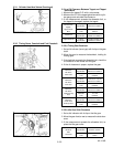
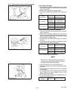
2.3.1.j V alve Spring Setting Load
1. Place the valve spring on a tester and compress it to
the same length it is actually compressed in the en-
gine.
2. Read the compression load on the gauge.
3. If themeasurement is less than theallowable limit, re-
place it.
Setting Load /
Setting Length
Factory
Specification
118N/35mm
12.0 kgf / 3 5 mm.
26.5 lbs. / 1.38 in.
Allowable
Limit
100 N / 35 mm
10.2 kgf / 3 5 mm.
22.5 lbs. / 1.38 in.
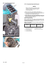
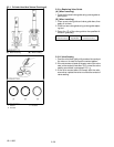
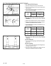
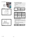
2.3.1.k Oil Clearance Between Rocker Arm and
Rocker Arm Shaft
1. Measure the rocker arm shaft O.D. with an outside
micrometer.
2. Measure therocker a rmI.D. with ainsidemicrometer ,
then calculate the oil clearance.
3. If the oil clearance exceeds the allowable limit, re-
place the rocker arm then measure the oil clearance
again. If the clearance is still out of specification, re-
place the rocker arm shaft.
Oil C learance
Rocker Arm/
Shaft
Factory
Specification
0.016 to 0. 045 mm
0.0063 to 0. 0017 in.
Allowable
Limit
0.10 mm
0.0039 in.
Rocker Arm
Shaft O.D.
Factory
Specification
13.973 to 13. 984 mm
0.55012 to 0. 55055 in.
Rocker Arm I.D.
Factory
Specification
14.000 to 14. 018 mm
0.55119 to 0.55188 in.
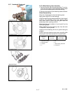
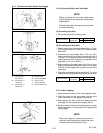
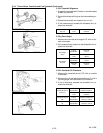
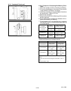
2.3.1.l Push Rod Alignment
1. Place the push rod on V blocks
2. Measure the push rod alignment.
3. If the measurement exceeds the allowable limit, re-
place the push rod.
Push Rod
Alignment
Allowable
Limit
0.25 mm
0.0098 in.