


2--28
62--11362
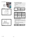
2.3.4 Crankshaft
A
B
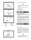
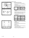
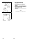
2.3.4.a Crankshaft End Clearance
1. Push on theend of the crankshaft to seat it toward the
flywheel end of the engine block.
2. Attach, thenzeroa d ialindicatoron the forward endof
the crankshaft.
3. Measure the end play by pulling the crankshaft for-
ward.
4. If the measurement exceeds the allowable limit re-
place the thrustwashers.
Crankshaft S ide
Clearance
Factory
Specification
0.15 to 0.31 mm
0.0059 to 0. 012 in.
Allowable
Limit
0.5 mm
0.02 in.
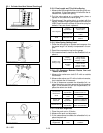
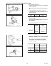
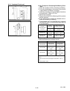
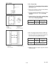
(Reference)
Oversize dimensions of crankshaft journal.
Oversize 0.2mm / 0.008 in. 0.4mm / 0.02 in.
Dimension A
54.5 to 54. 7 mm
2.146 to 2. 153 in.
54.6 to 54. 8 mm
2.150 to 2. 157 in.
Dimension B
26.20 to 26. 25 mm
1.032 to 1. 033 in.
26.40 to 26. 45 mm
1.040 to 1. 041 in.
Dimension C
2.8 to 3.2 mm radius
0.11 to 0.12 in.
radius
2.8 to 3.2 mm radius
0.11 to 0.12 in.
radius
The crankshaft journal must be fine--finished to higher than
0.4--S.
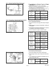
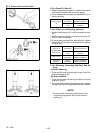
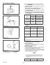
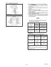
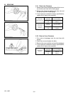
2.3.4.b Crankshaft Alignment
1. Support the crankshaft with V blocks on a surface
plate at both end journals. Set a dial indicator with i ts
tip o n the intermediate journal, perpendicular to the
journal.
2. Rotate the crankshaft on the V blocks and get the
misalignment (half of the measurement).
3. If the misalignment exceeds the allowable limit, re-
place the crankshaft.
Crankshaft
Alignment
Allowable
Limit
0.02 mm
0.0008 in.