


2--21
62--11362
2.3.1 Cylinder Head And Valves (Continued)
ab
(1)
(2)
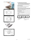
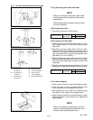
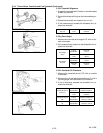
a. 0. 26 rad.(15°)or
0.52 rad.(30°)
b. 0.79 rad.(45°)or
1.0 rad.(60°)
c. 0. 52 rad.(30°)or
0.26 rad.(15°)
A. Check Contact
B. Correct Seat W idth
C Check Contact
1. Valve Seat Width
2. Identical Dimensions
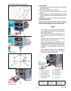
2.3.1.g Correcting Valve and Valve Seat
NOTE
Before correcting the valve seat, make certain
that the valve and valve guide are within factory
specifications.
After correcting the valve seat, be sure tocheck
the valve recessing.
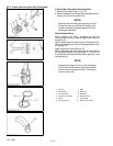
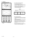
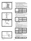
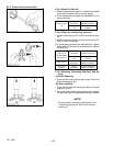
(A) Correcting the Valve
1. Correct the valve with a valve grinder.
Valve Face Angle
Factory
Specification
IN. 0.79 rad / 45°
EX. 0.79 rad / 45°
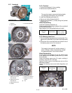
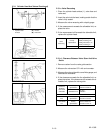
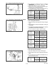
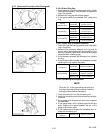
(B) Correcting the V alve Seat
1. Slightly correct the valve seat surface with a 1.0 rad.
(60°) ( intake valve) or 0.79 rad. (45°) (exhaust valve)
seat cutter .
2. Resurface the seat surface with a 0.52 rad. (30°)
valve seat cutter to the Intake valve seat and with a
0.26 rad. (15°) valve seat cutter to the exhaust valve
seat so that the width is close to the specified valve
seat width (2.12 mm, 0.0835 in.).
3. After resurfacing the seat, apply a thin film of valve
lapping compound between the valve and the seat,
then use a valve lapping tool to seat the valve to the
valve seat.
4. Check thevalveseatingwith prussianblue. Thevalve
seating should show good contact all the way around.
Valve Face Angle
Factory
Specification
IN. 0.79 rad / 45°
EX. 0.79 rad / 45°
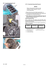
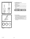
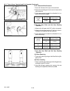
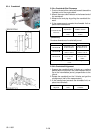
2.3.1.h V alve Lapping
1. Apply compound evenly to the valve lapping surface.
2. Insert the valve into the valve guide. Lap the valve
onto its seat with a valve lapper or bolt driver .
3. After lapping the valve, wash the compound away
and apply oil, then repeat valve lapping with oil.
4. Apply prussian blue to the contact surface to check
the contact pattern, if it is less than 70%, repeat valve
lapping again.
NOTE
When valve lapping is performed, be sure to
check the valve recessing and adjust the valve
clearance after assembling the valve.