


2--6
62--11362
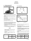
2.2.4 Injection Pump and Gear Case
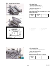
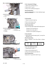
2.2.4.a Injection Pump
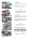
1. Remove the fuel speed solenoid (2) and hi--idling
body (3).
2. Remove the engine stop lever (5) and stop solenoid
guide (6).
3. Remove the fuel injection pump assembly (7).
NOTE
Remove the injection pump assembly (7) after
removing the fuel speed solenoid (2) and hi--id-
ling body (3), engine stop lever (5) and stop
solenoid guide (6).
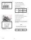
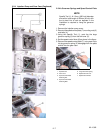
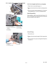
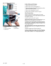
When Reassembling
Install the fuel speed solenoid (2), the hi--idling body (3)
and the stop solenoid guide (6) after Installing the
injection pump (7).
Replace the hi--idling body gasket (4) with a new one.
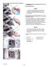
Install the fuel speed solenoid guide (6) and then the
stop lever (5) into the gear case. Cycle the stop lever to
insure that it functions.
NOTE
When installing the fuel speed solenoid ( 2), use
care to keep the O--ring (1) in place.
Be sure to insert the push rod of the stop solenoid into
the hole at the center of the solenoid guide (6).
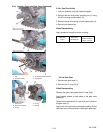
Tightening
Torque
Hi--idling B ody
45.0 to 49. 0 N
.
m
4.5to5.0kgf
.
m
33 to 36 ft--lbs
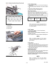
1. O--ring
2. Fuel Speed Solenoid
3. Hi--Idling Body
4. Hi--Idling Body Gasket
5. Stop Lever
6. Stop Solenoid Guide
7. Injection Pump Assembly