


2--26
62--11362
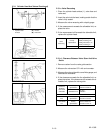
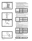
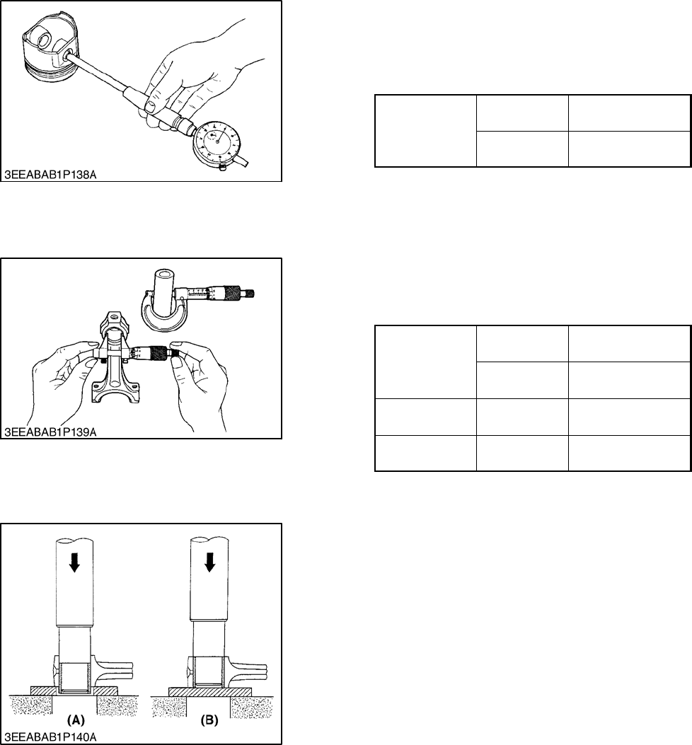
2.3.3 Piston and Connecting Rod
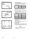
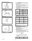
2.3.3.a Piston Pin Bore I.D.
1. Measure the piston pinboreI.D. in both thehorizontal
and vertical directions with a cylinder gauge.
2. If the measurement exceeds the allowable limit, re-
place the piston.
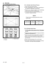
Piston Pin Bore
I.D.
Factory
Specification
25.000 to 25. 013 mm
0.98426 to 0. 98476 in.
Allowable
Limit
25.05 mm
0.9862 in.
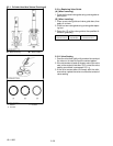
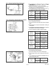
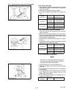
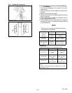
2.3.3.b Piston Pin and Bushing Clearance
1. Measure thepistonpin O.D. withan outsidemicrome-
ter.
2. Measure the connecting rod small end bushing I.D.
with an inside micrometer.
3. If the clearance exceeds the allowable limit, replace
the bushing. If theclearanceis still excessive, replace
the piston pin.
Piston Pin to
Small End Bush-
ing Clearance
Factory
Specification
0.014 to 0. 038 mm
0.00055 to 0. 00150 in.
Allowable
Limit
0.15 mm
0.0059 in.
Piston Pin O.D.
Factory
Specification
25.002 to 25. 011 mm
0.98433 to 0. 98468 in.
Small End
Bushing I.D
.
Factory
Specification
25.025 to 25. 040 mm
0.98523 to 0. 98582 in.
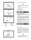
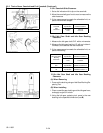
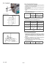
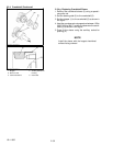
2.3.3.c Replacing Connecting R od Small End Bu-
shing
(A) When Removing
1. Press out the small end bushing using a Small End
Bushing Replacing Tool.
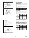
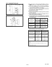
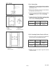
(B) When Installing
1. Clean a new small end bushing and bore, and apply
engine oil to both.
2. Using the small end bushing replacing tool, press in
the new bushing to the specified dimension (see B).
NOTE
Be sure to align the bus hing so that the oil hole
in the bushing aligns with the oil port in the con-
necting rod.