


2--31
62--11362
2.3.4 Crankshaft (Continued)
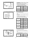
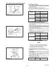
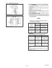
2.3.4.f Crankshaft Journal to Crankshaft Bearing
#2 Clearance
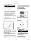
1. Put a strip of plastigage on the center of the crank-
shaft journal.
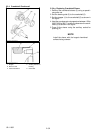
2. Install the bearing case and tighten the bolts to spe-
cification.
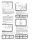
3. Remove the bearing case again.
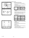
4. Measure the amount of t he flattening withthe scaleto
get the clearance.
5. If the measurement exceeds the allowable limit re-
place crankshaft bearing #2.
6. If the allowable limit is not attainable with a standard
size bear ing, install an undersize bearing by referring
to the table below.
NOTE
Be sure not to move the crankshaft w hile the
bearing bolts are tightened.
Crankshaft
Journal to #2
Bearing
Clearance
Factory
Specification
0.040 to 0. 104 mm
0.00158 to 0. 00409 in.
Allowable
Limit
0.2 mm
0.0079 in.
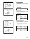
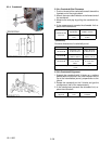
Crankshaft
Journal O.D
.
Factory
Specification
59.921 to 59. 940 mm
2.3591 to 2. 3598 in.
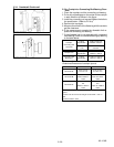
Crankshaft
Bearing B earing
I.D.
Factory
Specification
59.980 to 60. 025 mm
2.3615 to 2. 3631 in.
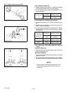
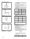
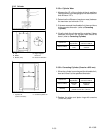
(Reference)
Undersize dimensions of crankshaft journal.
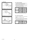
Oversize 0.2mm / 0.008 in. 0.4mm / 0. 016 in.
Dimension A
2.8 to 3.2 mm radius
0.11 to 0.12 in.
radius
2.8 to 3.2 mm radius
0.11 to 0.12 in.
radius
Dimension B
1.0 to 1.5 mm radius
0.040 to 0. 059 in.
radius
1.0 to 1.5 mm radius
0.040 to 0. 059 in.
radius
Dimension C
59.721 to 59. 740
mm
2.3513 to 2. 3519 in.
59.521 to 59. 540
mm
2.3433 to 2. 3440 in.
The crankshaft journal must be fine--finished to higher than
0.4--S.
*Holes to be de--burred and edges rounded with 1.0 to 1.5 mm
(0.040 0.059 in.) relief.