


2--5
62--11362
2.2.3 Cylinder Head And Valves (Continued)
1
2
3
4513 12
1689
17
11
157
6
10
14
18
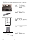
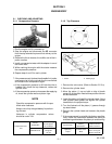
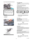
1. Hose Clamp
2. Filter--Drier Inlet
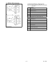
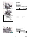
A: Gear C ase Side
B: Flywheel Side
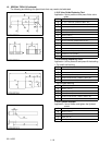
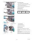
2.2.3.e Cylinder Head
1. Loosen the hose clamp (1), and remove the water re-
turn pipe (2).
2. Remove the cylinder head bolts in the order of ( 18)to
(1).
3. Lift up the cylinder head and remove.
4. Remove the cylinder head gasket (3).
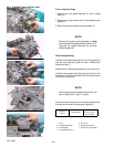
When Reassembling
Replace the cylinder head gasket (3) with a new one.
Apply oil to, then re--install the cylinder head bolts.
T ighten the cylinder head bolts in sequence starting
from the center in the order of (1)to(18).
T ighten the head bolts uniformly or head warpage may
occur.
Tightening
Torque
Cylinder Head
Bolt
93.1 to 98. 0 N
.
m
9.5 to 10. 0 kgf
.
m
68.7 to 72. 3 ft--lbs
NOTE
When replacing thecylinderhead gasket (3),be
sure you are using a new gasket that matches
the original gasket.
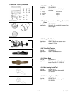
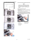
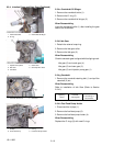
2.2.3.f Tappets
1. Remove the tappets (1) from the crankcase.
When Reassembling
Visually check the contact between the tappets (1) and
individual cam lobes.
Coat the tappets with engine oil before installing them.
NOTE
When re--installing tappets i nto the engine,
make s ure that they are re--installed in their ori-
ginal location.
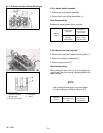
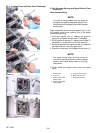
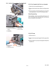
2.2.3.g V alves
1. Remove the valve caps (3).
2. Remove the valve spring collet ( 4), pushing the valve
spring retainer (5) b ythevalve spring compressor(1).
3. Remove the valve spring retainer (5), valve spring (6)
and valve stem seal (2).
4. Remove the valve (7).
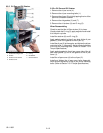
When Reassembling
Clean the valve stem and the valve guide. A pply engine
oil to the valve stem when reassembling.
After installing the v alve spring c ollets (4), lightly tap the
stem with a plastic hammer to assure the collets have
seated on the valve stem.
NOTE
When re--installing valves into the engine,
make sure that they are re--installed in their
original location.