


2--10
62--11362
2.2.4 Injection Pump and Gear Case (Continued)
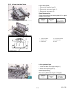
1. Crankshaft Collar
2. O--rin
g
3. Crankshaft Oil Slinger
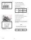
1. Injection Pump Gear
2. Idle Gear
3. Cam Gear
4. Crank Gear
5. Oil Pump Drive Gear
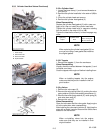
1. Camshaft S et Screw 2. Camshaft
1. Oil Pipe
2. Fuel Feed Pump
3. O--ring
4. Fuel Feed Pump Holder
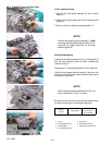
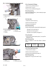
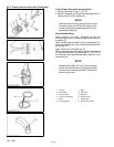
2.2.4.e Crankshaft Oil Slinger
1. Remove the crankshaft collar (1).
2. Remove the O--ring (2).
3. Remove the crankshaft oil slinger (3).
When Reassembling
Insert the crankshaft collar (1) after installing the gear
case to the crankcase.
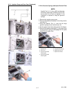
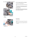
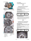
2.2.4.f Idle Gear
1. Detach the external snap ring.
2. Remove the idle gear collar.
3. Remove the idle gear (2).
When Reassembling
Check to see each gear is aligned with its aligningmark.
Idle gear (2) and crank gear (4)
Idle gear (2) and cam gear (3)
Idle gear (2) and injection pump gear (1)
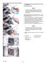
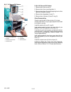
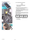
2.2.4.g Camshaft
1. Remove the camshaft retaining bolt (1) and pull the
camshaft (2) out.
When Reassembling
Refer to installation of Idle Gear (Refer to Section
2.2.4.f).
Tightening
Torque
Camshaft
retaining bolt
24 to 27 N
.
m
2.4to2.8kgf
.
m
18 to 20 ft--lbs
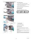
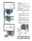
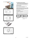
2.2.4.h Fuel Feed Pump Holder
1. Disconnect the oil pipe (1).
2. Remove the fuel feed pump (2).
3. Remove the fuel feed pump holder (4).
When Reassembling
Replace the O--rings (3) with new O--rings.