


2--15
62--11362
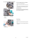
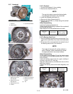
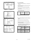
2.2.7 Crankshaft
1. Flywheel
2. Fl
y
wheel Bolt
3. Flywheel G uide Bolts
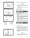
1. Bearing Case Cover
Mounting Bolt
2. Bearing Case Cover
Mounting bolt
3. Bearing Case Cover
4. Oil Seal
5. Bearing Case Gasket
6. Bearing Case Cover
Gasket
(a). Top
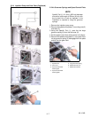
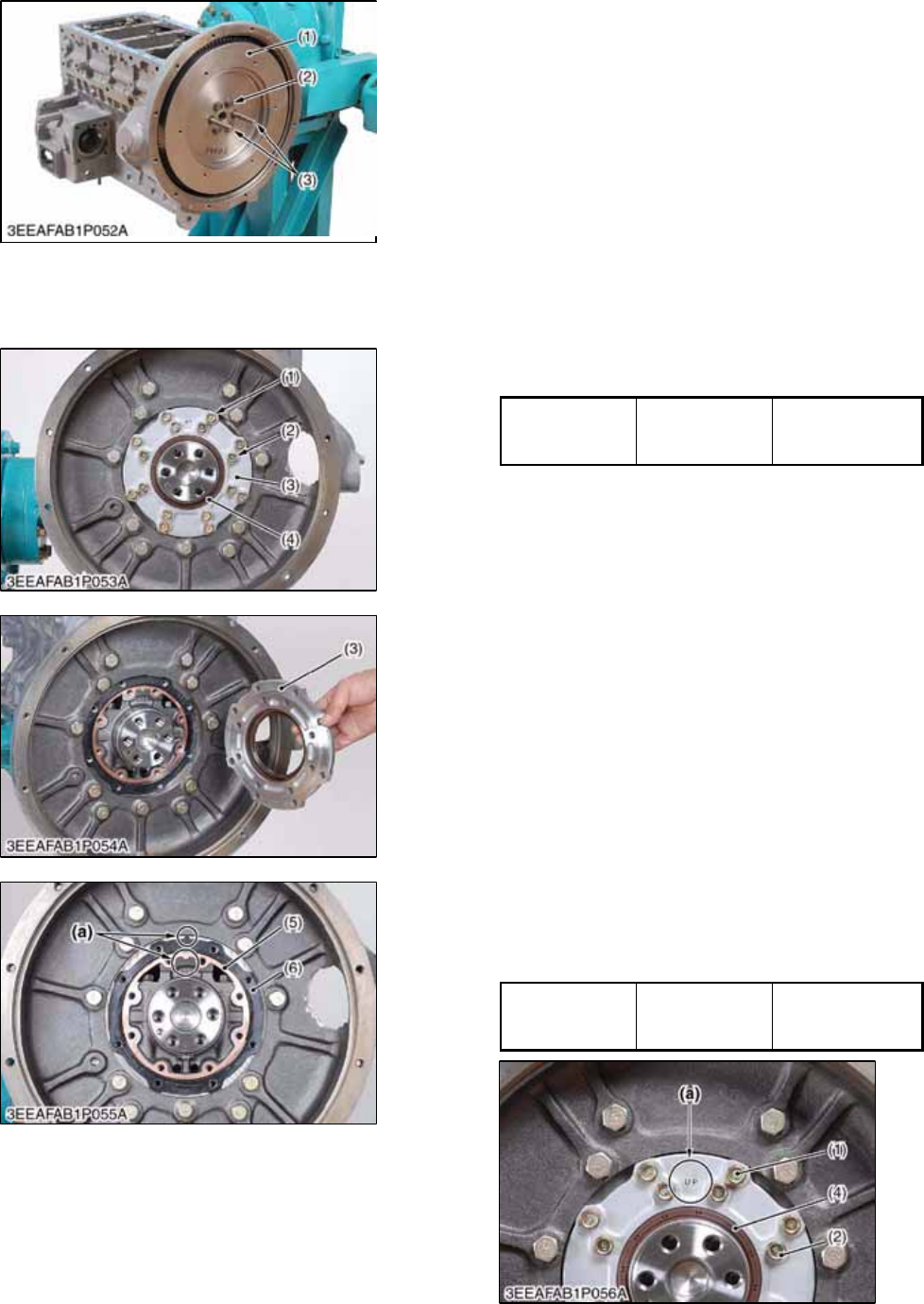
2.2.7.a Flywheel
1. Prevent the flywheel (1) from rotating.
2. Remove two flywheel bolts (2).
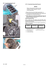
NOTE
The use of air tools to remove the flywheel bolts
may damage the threads in the crankshaft.
3. Install two flywheel guide bolts (3).
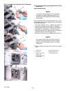
4. Remove all of the flywheel bolts (2).
5. Remove the flywheel (1) slowly along the flywheel
guide bolts (3).
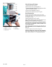
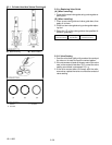
When Reassembling
Install two flywheel guide bolts (3).
Check to see that the mating surfaces of the crankshaft
and flywheel are clean.
Apply engine oil to the flywheel bolts and install.
Tightening
Torque
Flywheel Bolts
98.0 to 107. 8 N
.
m
10.0 to 11.0 kgf
.
m
72.3 to 79. 5 ft--lbs
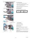
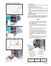
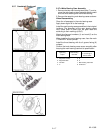
2.2.7.b Bearing Case Cover
1. Remove thebearing case covermountingbolts. First,
remove the inside bolts ( 2) and then the outside bolts
(1).
2. Screw two of the removed bolts into the bolt hole of
the bearing case cover (3) to remove it.
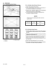
NOTE
The length o f the inside (2) and the outside (1)
bolts is different. When reassembling reinstall
the appropriate bolt in the correct location.
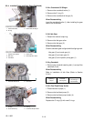
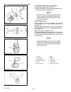
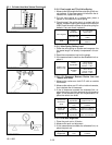
When Reassembling
Fit the bearing case gasket (5) and the bearing case
cover gasket (6) to the bearing case cover (3). Orient
them correctly.
Install the bearing case cover (3), again orienting it
correctly, using the “UP” mark (a).
Apply oil to the oil seal (4), and take care not to roll the
seal when installed.
T ighten the bearing case cover bolts diagonally and
evenly.
Tightening
Torque
Bearing C ase
Cover Mounting
bolt
24 to 27 N
.
m
2.4to2.8kgf
.
m
18 to 20 ft--lbs