


2--13
62--11362
2.2.6 Piston and Connecting Rod
6
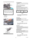
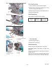
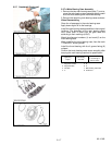
2.2.6.a Pistons
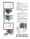
1. Completely remove the carbon ridge (1) at the top of
the cylinder walls.
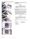
2. Remove the connecting rod cap (3).
3. Turn the flywheel and br ing the piston to top dead
center.
4. Push the piston out by lightly tapping the connecting
rod from thebottom of the crankcasewith thegrip of a
hammer.
5. Repeat the procedure for the other three cylinders.
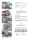
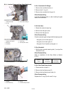
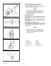
When Reassembling
Liberally c oat the piston and piston r ings with engine oil.
When inserting the piston into the cylinder, face the
mark on the connecting rod to the injection pump.
NOTE
If re--installing the original piston assemblies
into the engine be sure that t hey are returned to
their original cylinder.
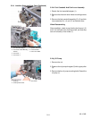
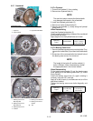
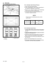
Place the piston rings with their gaps at 2.09
rad. (120°) from the piston pin’s d irection as
shown.
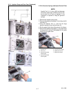
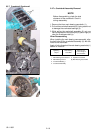
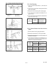
Carefully insert the pistons into the cylinders
using the piston ring compressor (7).
When inserting thepiston intothecylinder avoid
damaging the molybdenum disulfide coating on
the piston skirt. This coating is useful in mini-
mizing the clearance between the piston and
cylinder.
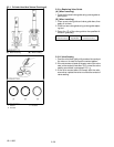
When replacing a piston, use a replacement
piston with the same code number. The piston
ID mark (6) is on top of the piston.
1. Carbon
2. Connecting R od Bolt
3. Connecting R od Cap
4. Connecting R od
5. Molybdenum Disulfide
CoatingonPistonSkirt
6. Piston ID Mark
7. Piston R ing Compressor
(A) Top Ring Gap
(B) Second Ring Gap
(C)OilRingGap
(D) Piston Pin Hole
(
a
)
2.09 rad.
(
120°
)
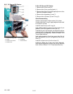
Tightening
Torque
Connecting
Rod Bolt
45 to 49 N
.
m
4.5to5.0kgf
.
m
33 to 36 ft--lbs