


2--29
62--11362
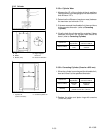
2.3.4 Crankshaft (Continued)
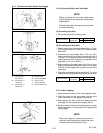
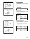
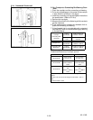
2.3.4.c C rankpin t o Connecting R od Bearing C lear-
ance
1. Clean the crankpin and the connecting rod bearing.
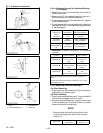
2. Put a strip of plastigage on the center of the c rankpin
in each direction as shown in the figure.
3. Install the connecting rod cap and tighten the bolts to
the specification. (Refer to 2.2.6.a)
4. Remove the cap again
5. Measure the amount of t he flattening withthe scaleto
get the clearance.
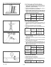
6. If the measurement exceeds the allowable limit re-
place the connecting rod bearing.
7. If the allowable limit is not attainable with a standard
size bear ing, install an undersize bearing by referring
to the table below.
Crankpin/
Connecting Rod
Clearance
Factory
Specification
0.025 to 0. 087 mm
0.00099 to 0. 0034 in.
Allowable
Limit
0.2 mm
0.0079 in.
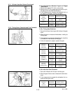
Crankpin O.D.
Factory
Specification
46.959 to 46. 975 mm
1.8488 to 1. 8494 in.
Connecting Rod
Bearing I.D.
Factory
Specification
47.000 to 47. 046 mm
1.8504 to 1. 8522 in.
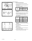
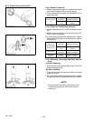
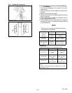
(Reference)
Undersize dimensions of crankpin journal.
Undersize 0.2mm / 0. 008 in. 0.4mm / 0.02 in.
Dimension A
3.3to3.7mm
0.13 to 0. 14 in.
3.3to3.7mm
0.13 to 0. 14 in.
Dimension B
1.0 to 1.5 mm radius
0.040 to 0. 059 in.
radius
1.0 to 1.5 mm radius
0.040 to 0. 059 in.
radius
Dimension C
46.759 to 46. 775
mm
1.8409 to 1. 8415 in.
radius
46.559 to 46. 575
mm
1.8331 to 1. 8336 in.
radius
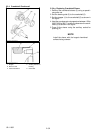
The crankshaft journal must be fine--finished to higher than
0.8--S.
*Holes to be de---burred and edges rounded with 1.0 to 1.5
mm
(0.040 to 0.059 in. relief.