


2--14
62--11362
2.2.6 Piston and Connecting Rod (Continued)
7
8
7
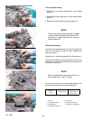
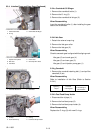
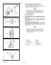
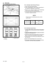
2.2.6.b Piston Ring and Connecting Rod
1. Remove the piston rings (1), (2), (3).
2. Remove the piston pin (8) and then seperate the con-
necting rod (6) from the piston (5).
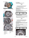
NOTE
Mark both the connecting rod and piston so that
if they are to be re--used that the original com-
bination ofparts will goback together. Do not in-
terchange used parts.
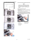
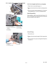
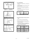
When Reassembling
When installing the rings, assemble so that the
manufacturer’s mark (12) near the gap faces the top o f
the piston (5).
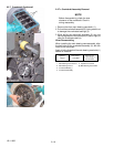
When installing theoil control ring (3) onto the piston (5),
place the expander joint (10) on the opposite side of the
oil ring gap (11).
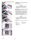
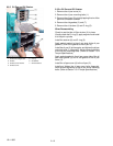
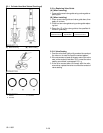
Apply engine oil to the piston pin (8).
When assembling the connecting rod (6) to the piston
(5), immersethepiston(5) inhot oil (80°C /176°F)for10
to 15 minutes, then assemble the piston, piston pin, and
connecting rod.
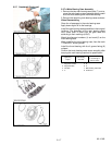
NOTE
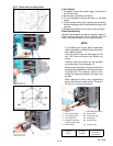
Assemble the piston (5) on to the connecting
rod (6) with the FW mark (9) facing the flywheel
end and the connecting rod mark ( 7) facing the
injection pump side.
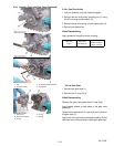
1. Top Ring
2. Second Ring
3. Oil Control Ring
4. Piston Pin Snap Ring
5. Piston
6. Connecting R od
7. Mar k
8. Piston Pin
9. F W Mark
10. Expander Joint
11. Oil Ring Gap
12. Manufacturer’s Mark