


2--23
62--11362
2.3.1 Cylinder Head And Valves (Continued)
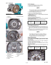
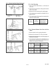
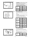
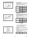
2.3.1.m Oil Clearance Between Tappet a nd T appet
Guide Bore
1. Measure the tappet O.D. with a micrometer.
2. Measure the I.D. of the tappet guide bore with acylin-
der gauge and calculate the clearance.
3. If the measurement exceeds the allowable limit, or
the tappet is damaged, replace the tappet.
Oil C learance
Tappet/
Tappet Guide
Bore
Factory
Specification
0.020 to 0. 062 mm
0.00079 to 0. 00244 in.
Allowable
Limit
0.07 mm
0.003 in.
Tappet O.D.
Factory
Specification
23.959 to 23. 980 mm
0.94327 to 0. 94409 in.
Tappet Guide I.D.
Factory
Specification
24.000 to 24. 021 mm
0.94489 to 0. 94570 in.
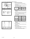
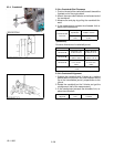
2.3.2 Timing Gears, Camshaft and Fuel Camshaft
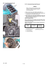
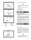
2.3.2.a Timing Gear Backlash
1. Set a dial indicator (lever type) with its tip on the gear
tooth.
2. Move the gear to measure the backlash, holding its
mating gear.
3. If the backlash exceeds the allowable limit, check the
oil clearance of the shafts and the gear .
4. If the oil clearance is proper, replace the gear.
Backlash/
Idle Gear/
Crank Gear
Factory
Specification
0.0415 to 0. 1122 mm
0.00163 to 0. 00442 in.
Allowable
Limit
0.15 mm
0.0059 in.
Backlash/
Idle Gear/
Cam Gear
Factory
Specification
0.0415 to 0. 1154 mm
0.00163 to 0. 00454 in.
Allowable
Limit
0.15 mm
0.0059 in.
Backlash/
Idle Gear/
Injection Pump
Gear
Factory
Specification
0.0415 to 0. 1154 mm
0.00163 to 0. 00454 in.
Allowable
Limit
0.15 mm
0.0059 in.
Backlash/
Crank Gear/
Oil P ump Gear
Factory
Specification
0.0415 to 0. 1090 mm
0.00163 to 0. 00429 in.
Allowable
Limit
0.15 mm
0.0059 in.
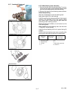
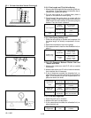
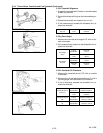
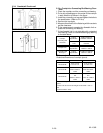
2.3.2.b Idle Gear Side Clearance
1. Set a dial indicator with its tip on the idle gear.
2. Move the gear front to r ear to measure the side clear-
ance.
3. If the measurement exceeds the allowable limit, re-
place the idle gear collar.
Idle Gear
Side
Clearance
Factory
Specification
0.12 to 0.48 mm
0.0047 to 0. 018 in.
Allowable
Limit
0.9 mm
0.04 in.