7
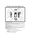
9. Page Button (PAGE): Scrolls sequentially through menu pages in the forward direction,
and also provides access to a shortcut display for easy acquisition of main GPS displays.
10. Battery Compartment Cover: Allows access to four AA batteries when removed.
11. DC6V Jack: It accepts a DC-to-DC vehicle cigarette lighter battery eliminator adapter.
12. Battery Charging Contacts: Provide in-unit charging of batteries when unit is placed in
charging stand.
13. LCD Display: Displays the various pages, menus, and modes of operation.
14. Power On/Off/Mark Button ( /M): Provides a means of turning the unit on and off;
during GPS operation, this button is also used to mark a current position for save purposes,
or for sending your location to another unit during tracking/GO TO operation.
15. Monitor (MON) Button: Provides a means of temporarily bypassing the squelch setting
and play all signals on a given GMRS channel.
16. Belt Clip Attachment Stud: Allows unit to be attached to the belt clip.
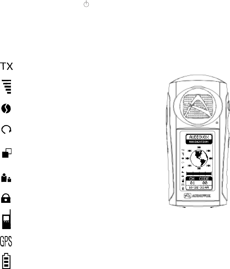
Operational Status Icon Definition
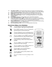
This icon appears during GMRS/GPS operation when
an audio or location radio signal is being transmitted.
During GMRS operation, this icon indicates the
relative strength of a received radio signal.
This icon indicates that a user is contacting you with a
unit that is set to the same channel and CTCSS code.
This icon appears during GMRS operation to
indicate the channel scan mode has been activated.
This icon appears during GMRS operation to
indicate the Priority Channel Scan mode has been
activated.
This icon appears during GMRS operation to
indicate the VOX mode is activated.
This icon appears during GMRS operation to
indicate the Key Lock mode is activated.
This icon appears when the RADIO ONLY or
RADIO + GPS mode is operational.
This icon appears when the GPS or RADIO + GPS
mode is operational.
This icon indicates the current strength of the
battery.


