2-47
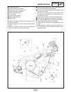
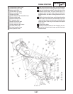
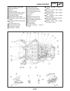
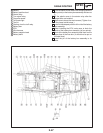
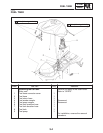
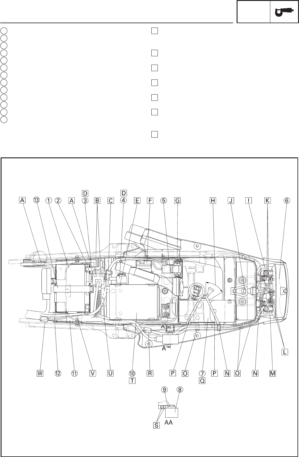
1 Battery
2 Battery positive lead
3 Starter relay
4 Turn signal relay
5 Pressure sensor
6 Tail/brake light
7 Tool kit
8 Starting circuit cut-off relay
9 Battery box
10 ECU
11 Wire harness
12 Battery negative lead
13 Battery band
CABLE ROUTING
SPEC
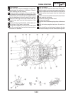
A Push the starter motor lead in the clamping sections
(two points) or the battery box assembly and secure
it.
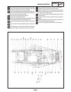
B Fit the plastic cover in the starter relay after the
flange bolts are installed.
C Make sure to clamp the wire harness. (Tighten it un-
til the clamp latchet stops.)
D Install to the deepest position of the rib of the battery
box assembly.
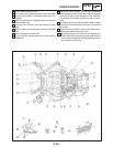
E When installing the ECU, make sure to hook the
pawls of the battery box assembly (at four points).
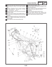
F Hook of the battery box assembly shall hook on the
upper face of the fuse box. (It should not be put on
the side face.)
G Install the pin of the battery box assembly to its
base.


