


8-41
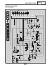
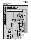
SIGNALING SYSTEM
ELEC
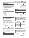
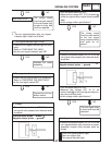
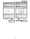
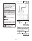
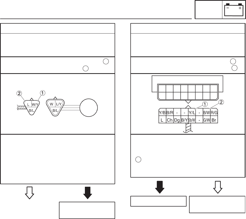
2. Speed sensor
SConnect the pocket tester (DC 20 V) to the
speed sensor coupler (wire harness side)
as shown.
Replace the speed
sensor.
NO
YES
Positive tester probe ! white/yellow
Negative tester probe ! blue
1
2
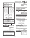
STurn the main switch to “ON”.
SElevate the rear wheel and slowly rotate it.
SMeasure the voltage (DC 5 V) of blue and
white/yellow. With each full rotation of the
rear wheel, the voltage reading should cycle
from 0.6 V to 4.8 V to 0.6 V to 4.8 V.
SDoes the voltage reading cycle correctly?
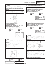
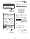
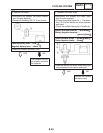
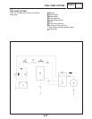
3. Voltage
SConnect the pocket tester (DC 20 V) to the
meter assembly coupler (wire harness
side) as shown.
Replace the meter
assembly.
YES
NO
Positive tester probe ! yellow/blue
Negative tester probe ! black/white
1
2
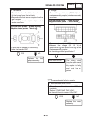
STurn the main switch to “ON”.
SElevate the rear wheel and slowly rotate it.
SMeasure the voltage (DC 5 V) of yellow/blue
on the meter assembly coupler (wire har-
ness side).
SIs the voltage within specification?
1
This circuit is OK.