


8-36
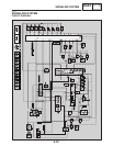
SIGNALING SYSTEM
ELEC
YES NO
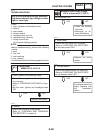
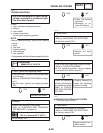
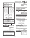
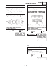
1. Tail/brake light (LEDs)
SCheck the tail/brake light for continuity.
Refer to “CHECKING THE LEDs”
SAre the tail/brake light OK?
Replace the
tail/brake light as-
sembly.
EAS00797
2. The tail/brake light fails to come on.
YES NO
2. Brake light switches
SCheck the brake light switches for continuity.
Refer to “CHECKING THE SWITCHES”.
SIs the brake light switch OK?
Replace the brake
light switch.
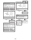
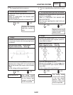
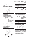
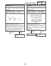
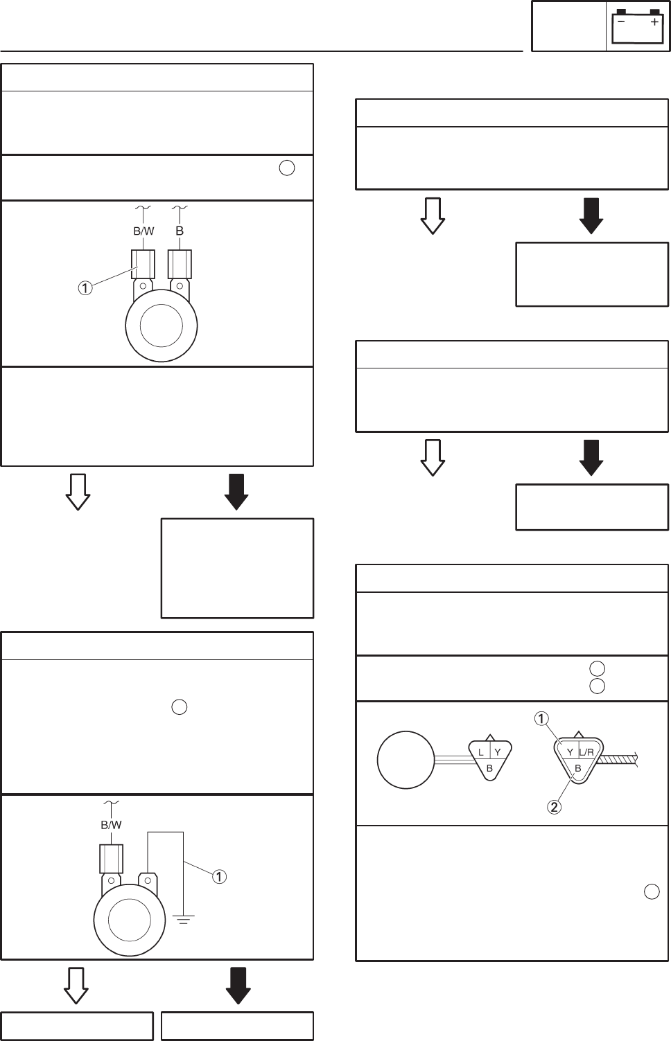
3. Voltage
SConnect the pocket tester (DC 20 V) to the
tail/brake light coupler (wire harness side)
as shown.
Positive tester probe ! yellow
Negative tester probe ! black
1
2
STurn the main switch to “ON”.
SPull in the brake lever or push down on the
brake pedal.
SMeasure the voltage (DC 12 V) of yellow
on the tail/brake light coupler (wire harness
side).
SIs the voltage within specification?
1
YES NO
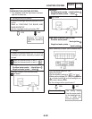
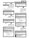
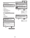
2. Voltage
SConnect the pocket tester (DC 20 V) to the
horn connector at the horn terminal as
shown.
The wiring circuit
from the main switch
to the horn connec-
tor is faulty and must
be repaired.
Positive tester probe ! black/white
Negative tester probe ! ground
1
STurn the main switch to “ON”.
SPush the horn switch.
SMeasure the voltage (DC 12 V) of
black/white at the horn terminal.
SIs the voltage within specification?
NOYES
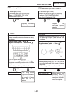
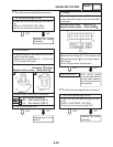
3. Horn
SDisconnect the black connector at the horn
terminal.
SConnect a jumper lead to the horn termi-
nal and ground the jumper lead.
STurn the main switch to “ON”.
SPush the horn switch.
SDoes the horn sound?
The horn is OK.
1
Replace the horn.