


8-38
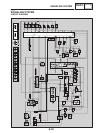
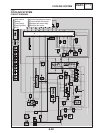
SIGNALING SYSTEM
ELEC
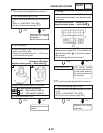
YES NO
The wiring circuit
from the turn signal
switch to the turn sig-
nal light connector is
faulty and must be
repaired.
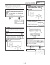
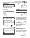
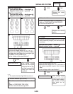
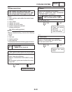
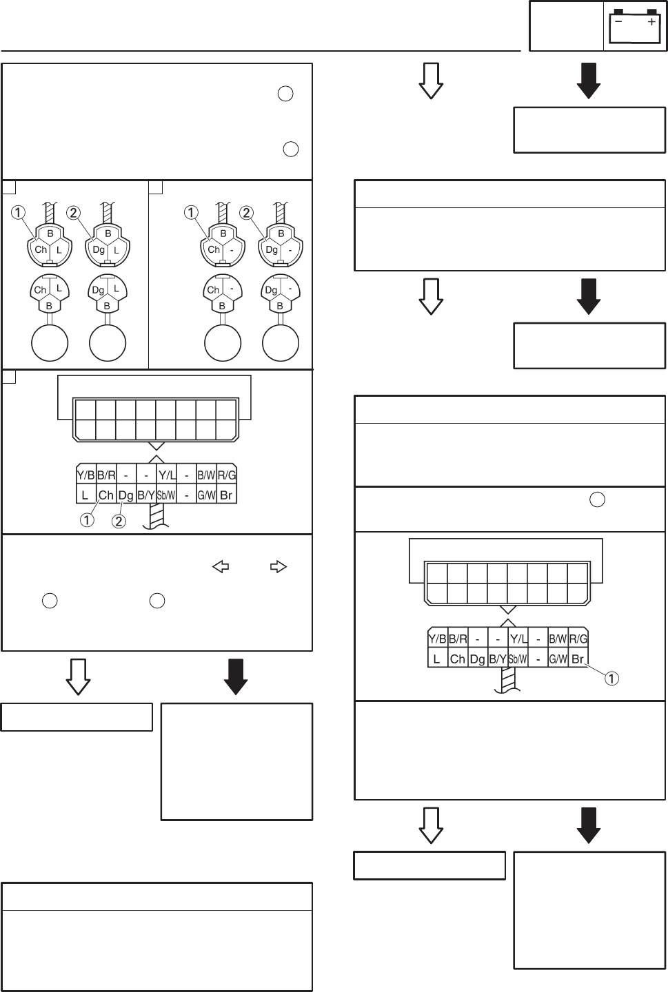
Left turn signal light
Positive tester probe ! chocolate
Negative tester probe ! ground
Right turn signal light
Positive tester probe ! dark green
Negative tester probe ! ground
1
2
STurn the main switch to “ON”.
SSet the turn signal switch to “ ” or “ ”.
SMeasure the voltage (DC 12 V) of the choco-
late or dark green at the turn signal light
connector (wire harness side).
SIs the voltage within specification?
1 2
This circuit is OK.
A B
C
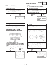
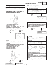
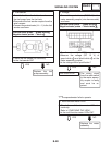
1. Neutral indicator light (LEDs)
SCheck the neutral indicator light for continu-
ity.
Refer to “CHECKING THE LEDs”
SAre the neutral indicator light OK?
EAS00801
4. The neutral indicator light fails to come on.
YES NO
Replace the meter
assembly.
YES NO
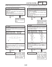
2. Neutral switch
SCheck the neutral switch for continuity.
Refer to “CHECKING THE SWITCHES”.
SIs the neutral switch OK?
Replace the neutral
switch.
YES NO
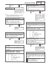
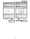
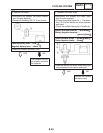
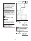
3. Voltage
SConnect the pocket tester (DC 20 V) to the
meter assembly coupler (wire harness side)
as shown.
The wiring circuit
from the main switch
to the meter assem-
bly coupler is faulty
and must be re-
paired.
Positive tester probe ! brown
Negative tester probe ! ground
1
STurn the main switch to “ON”.
SMeasure the voltage (DC 12 V) of brown at
the meter assembly coupler (wire harness
side).
SIs the voltage within specification?
This circuit is OK.