


3 Setting up the Receiver
14 5700/5800 GPS Receiver User Guide
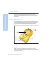
5700 GPS Receiver Operation
The power/serial data ports are all 7 pin 0-shell Lemo connectors. Both
Port 2 and Port 3 can accept external power. For more information, see
Default Settings, page 78. For more information, see Cables and
Connectors, page 85.
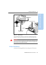
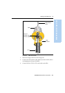
The TNC port connectors are color-coded for easy system setup.
Connect the yellow GPS antenna cable to the yellow TNC port marked
GPS, and connect the blue Range Pole antenna (RPA) cable to the blue
TNC connector marked RADIO. For more information, see the
following sections in this chapter.
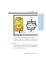
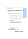
31.4 Bottom panel
Figure 3.5 shows the bottom panel of the 5700 receiver. This panel
contains the USB port, the CompactFlash port, and the compartments
for the two internal batteries.
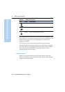
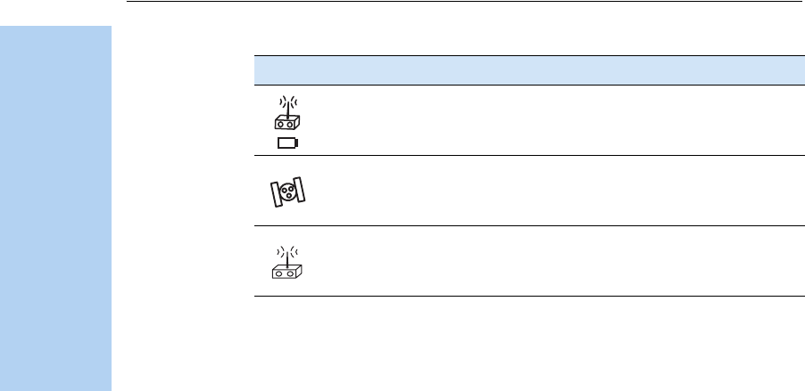
Port 3 External radio, power in
GPS GPS antenna
RADIO Radio communications antenna
Table 3.1 5700 receiver ports
Icon Name Connections