


10 Cables and Connectors
88 5700/5800 GPS Receiver User Guide
5700 GPS Receiver Operation
10.2Power/serial data cable
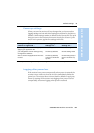
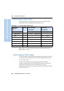
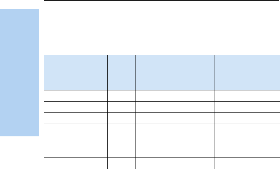
Table 10.2 gives pinout information for the power/serial data cable
(PN 32345), which is supplied with the 5700 receiver.
Note – Table 10.2 assumes that the cable is attached to the connector
labeled Port 1 or Port 3.
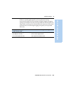
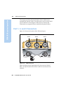
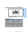
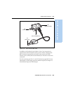
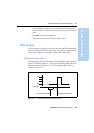
10.3Event Marker/1PPS Cable
The event marker/1PPS cable shown in Figure 10.3 provides a breakout
box with two BNC ( female) connectors for providing 1PPS input and
event marker output.
Connect a device that accepts 1PPS output pulses to the BNC
connector labeled 1PPS on the breakout box. Connect a device that
outputs event marker pulses to the 5700 receiver, such as a
photogrammetric camera, to the BNC connector labeled Event Marker
on the breakout box.
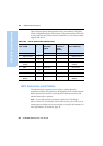
Table 10.2 Power/serial data cable pinouts
Lemo 0-shell
connector
7 Pin
Directio
n
DE9-F connector
7 Conductors
Power lead
2 Conductors
Pin Function Pin Color Function Color Function
1 Signal ground
↔
5 Brown Signal ground
2 GND
→
Black V-OUT
3TXD
→
2OrangeTXD
4RTS/TXD
→
8Blue RTS
5CTS/RXD
←
7 Green CTS
6 PWR
←
Red Power IN (+)
7RXD
←
3YellowTXD