


5700/5800 GPS Receiver User Guide 151
Cables and Connectors 19
5800 GPS Receiver Operation
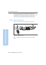
This data cable may be used for firmware upgrades and other
computer functions with the 5800. Power must be supplied to the unit
via Port 1, or from the internal battery.
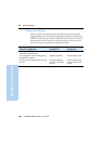
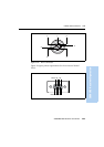
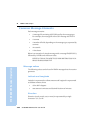
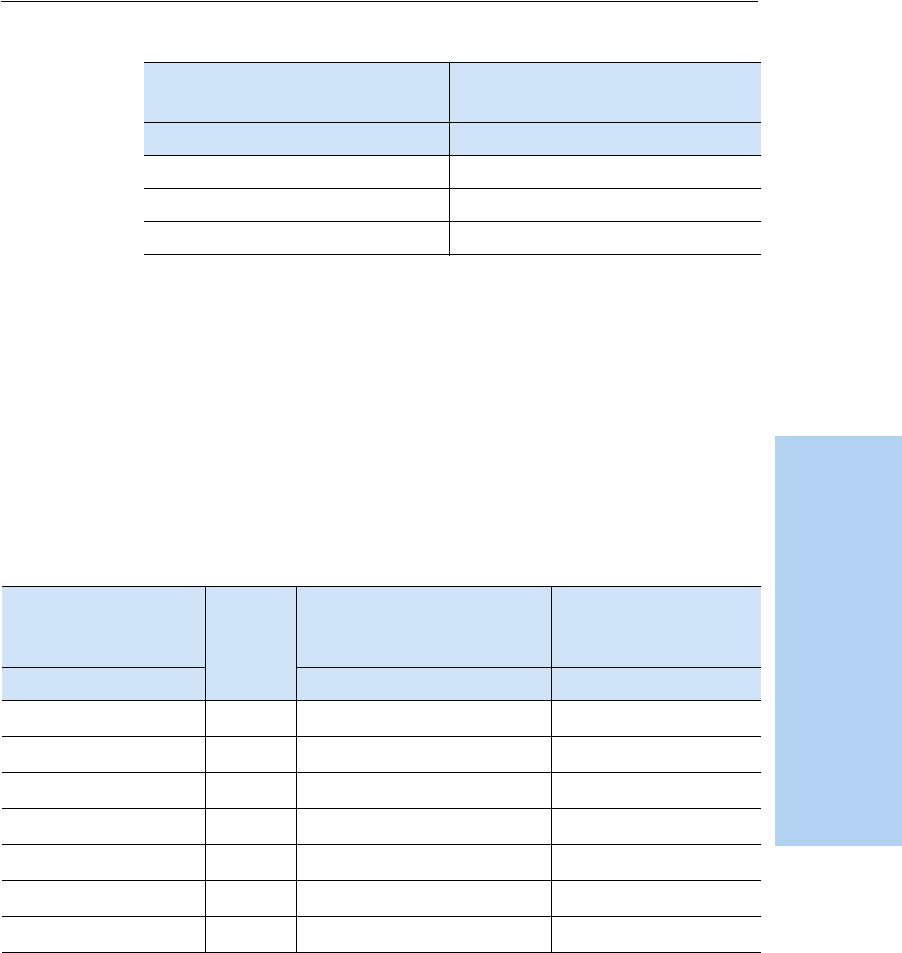
Note – Table 19.2 gives pinout information for the power/serial data cable,
(PN 32345) which is optional for use with the 5800 receiver. This cable may
be used for firmware upgrades through Port 1 of the 5800, while also
supplying external power.
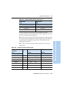
Note – Table 19.3 assumes that the cable is attached to the connector
labeled Port 1.
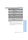
7 RTS5_232 8 CTS5_232
8 CTS5_232 7 RTS5_232
9 no connection RI5_232 9
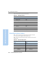
Table 19.3 Power/serial data cable pinouts
Lemo 0-shell
connector
7 Pin
Directio
n
DE9-F connector
7 Cond
Power lead
2 Cond
Pin Function Pin Color Function Color Function
1 GND
↔
5 Brown Signal ground
2 GND
→
Black V-OUT
3TX3_232
→
2OrangeTXD
4RTS/TXD
→
8Blue RTS
5CTS/RXD
←
7 Green CTS
6PWR_IN
←
Red Power IN (+)
7RX3_232
←
3YellowTXD
Table 19.2 Data-I/O cable pinouts (Continued)
DB-9 Female
9 Pin
DB-9 Female
9 pin
Pin Function Pin Function