


10 Cables and Connectors
90 5700/5800 GPS Receiver User Guide
5700 GPS Receiver Operation
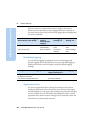
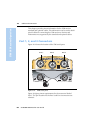
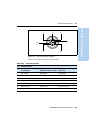
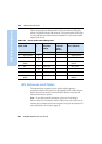
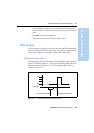
Table 10.3 gives pinout information for the event marker/1PPS cable
which is supplied with the 5700 receiver. The event marker/1PPS cable
is only used with the 5700 connectors labeled Port 1 ( for event marker
output) and Port 2.
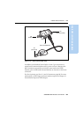
10.4GPS Antennas and Cables
The antenna that a receiver uses to collect satellite signals is
sometimes called a GPS antenna to distinguish it from a radio antenna.
Radio antennas are used for communication between receivers and
external networks or systems.
Note – To use older models of antennas, such as the Choke Ring or
Micro-Centered L1/L2 antennas, with a 5700 receiver, you need to use an
antenna power adapter and an external power source for the antenna. For
more information, see Antennas, page 32.
Table 10.3 Event marker/1PPS cable pinouts
P1: Lemo 7-Pin
Port 2 5700
Directio
n
P2: BNC-F
connector
(1PPS)
P3: BNC-F
connector
(Event
Marker)
P4: Lemo 7s
Port 2 extension
Pin 5700 function Pin Pin Pin Function
1 Signal ground
←
1 Signal ground
2 GND
→
GND GND 2 GND
3 Serial data out
(TXD2)
←
3 Serial data in
(TXD2)
41PPS
←
Center pin 4 No Connect
5Event Marker
↔
Center pin 5 No Connect
6Power IN (+)
→
6 Power IN (+)
7 Serial data in
(RXD2)
←
7 Serial data out
(RXD2)