


11 Cables and Connectors
122 5700 GPS Receiver User Guide
Reference
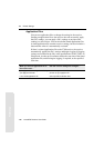
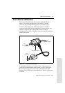
For Port 2 pinouts, see Port 1, 2, and 3 Connectors, page 118. For
more information on 1PPS input and event marker output, see
Chapter 13, Event Marker Input and 1PPS Output.
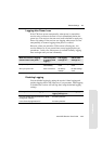
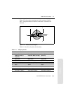
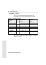
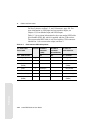
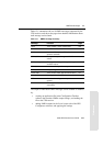
Table 11.3 gives pinout information for the event marker/1PPS cable
(Part Number 36451-00), which is supplied with the 5700 receiver.
The event marker/1PPS cable is only used with the 5700 connectors
labeled Port 1 (for event marker output) and Port 2.
Table 11.3 Event marker/1PPS cable pinouts
P1: Lemo 7-Pin
Port 2 5700
Direction P2: BNC-F
connector
(1PPS)
P3: BNC-F
connector
(Event Marker)
P4: Lemo 7s
Port 2 extension
Pin 5700 function Pin Pin Pin Function
1 Signal ground
←
1 Signal ground
2GND
→
GND GND 2 GND
3 Serial data out
(TXD2)
←
3 Serial data in
(TXD2)
4 1PPS
←
Center pin 4 No Connect
5 Event Marker
↔
Center pin 5 No Connect
6 Power IN (+)
→
6PowerIN(+)
7 Serial data in
(RXD2)
←
7 Serial data out
(RXD2)