


11 Cables and Connectors
120 5700 GPS Receiver User Guide
Reference
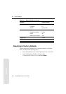
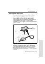
11.3 Data/Power Cable
Table 11.2 gives pinout information for the data/power cable
(Part Number 32345), which is supplied with the 5700 receiver.
Note – Table 11.2 assumes that the cable is attached to the connector
labeled Port 1 or Port 3.
Table 11.2 Data/power cable pinouts
Lemo 0-shell
connector
7Pin
Direction DE9-F connector
7 Cond
Power lead
2 Cond
Pin Function Pin Color Function Color Function
1 Signal ground
↔
5 Brown Signal ground
2GND
→
Black V-OUT
3TXD
→
2OrangeTXD
4RTS/TXD
→
8Blue RTS
5CTS/RXD
←
7GreenCTS
6PWR
←
Red Power IN (+)
7RXD
←
3 Yellow TXD