33
6 F 8 A 0 9 3 4
6. Operation
CAUTION
Do not touch the terminal board when power
is supplied.
Do not touch the main body when high
temperature fluid is being measured.
DON’T
Touching the terminal board
when power is supplied can
cause electric shock.
DON’T
The fluid raises the main body
temperature and can cause burns.
6.1 Preparatory check
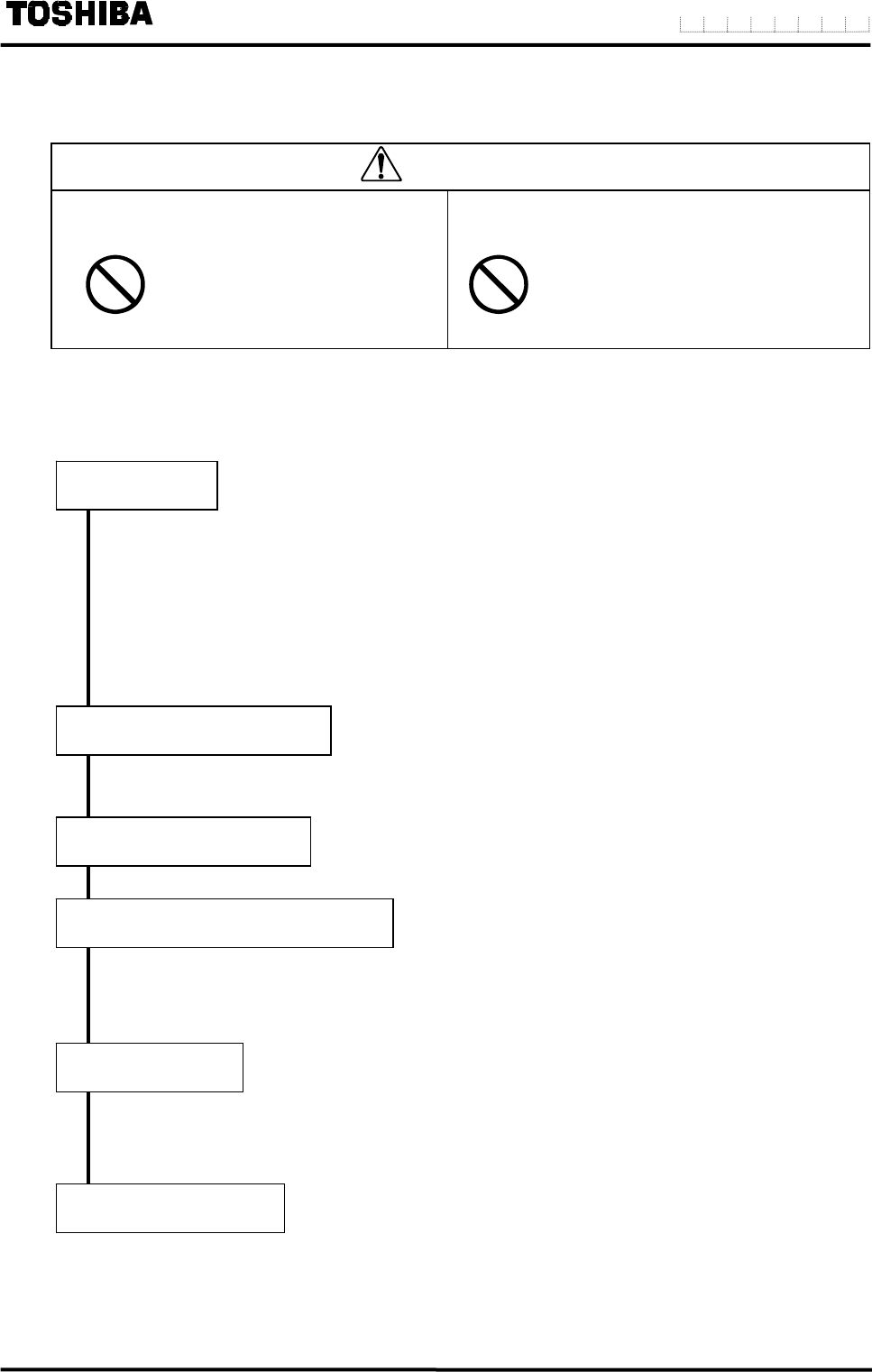
Follow the procedure described below to prepare before starting the flow measurement
Check the items listed below
Check the wiring between the converter and related instruments.
Make sure all the bolts of connection flanges on which the flowmeter is mounted
securely tightened.
Make sure the direction of flow arrow is in accordance with actual flow.
Make sure the flowmeter is grounded with 100 ohm or less ground resistance.
Make sure the converter housing covers are securely tightened.
Let the fluid go through the detector pipe. (Note 1)
When the detector is filled with the fluid, stop the fluid and keep it still in the detector pipe.
Make sure the power supply is as specified.
Check the configuration parameter settings. Refer to Chapter 7, “LCD Display and
Controls,” Chapter 8, “Configuration Parameter Setting,” and Chapter 11,
“Communications Function.”
Wait for 30 minutes to warm up the flowmeter. Then making sure the fluid holds still in the
detector pipe before starting the zero adjustment.
Refer to 6.2, “Zero Adjustment.”
After checking the items and conducting the zero adjustment as listed above, let the fluid go
through the detector pipe. Output (4–20 mA dc) directly proportional to the flow rate can be
obtained.
System Check
Placing System On-Stream
Supplying Electric Power
Checking Converter Parameters
Zero Adjustment
On-line measurement


