


28
6 F 8 A 0 9 3 4
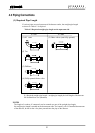
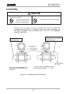
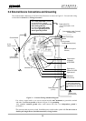
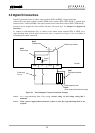
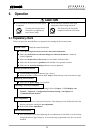
5.2 External Device Connections and Grounding
The terminal board connections of LF516/LF546 Flowmeter are shown in Figure 5.1. Proceed with wiring
as described in Section 5.4, “Wiring Procedure.”
Figure 5.1 External Wiring Schematic Diagram
* Use a heavy copper braid or wire (cross-sectional area 5.5 mm
2
minimum) to ground the terminal
and make it as short as possible as shown in Figure 5.1 for grounding.
Also, Avoid a common ground where earth current may flow. (An independent ground is
preferable.)
* The converter has no power switch. Install the power switch at the system side. Be sure to use a
double-pole/single-throw (both disconnection) wiring breaker.
Power supply
Wirin
g
breaker
(double-pole/single-throw)
Output si
g
nal cable
(CVV-S)
Current output
(4-20mAdc)
or PROFIBUS
NOTE:
To avoid 2-point grounding,
ground the shield of the output
cable basically at the receiving
side.
Digital output 1
Common for DI/DO
(100 ohm or less
ground resistance)
Digital output 2
Di
g
ital input
(20 to 30 Vdc)
Power cable
(
CVV
)
* For a 2-core cable, L1 and
L2 only.
IV wire
5.5mm
2
or more
Ground terminal
(100 ohm or less
ground resistance)
Converter unit
(100 ohm or less ground
resistance)
NOTE:
• When 3-core power cabel is used, do
not ground from the external
grounding terminal.(Perform grouding
at the receving side only).
• Only when a 2-core power cable is
used, perform grounding from the
external grounding terminal.
[Instrumentation panel: Customer]
(Receiving side)