


230
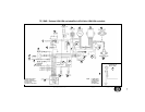
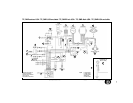
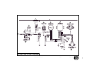
LEYENDA DEL ESQUEMA
ELÉCTRICO (TE 250-450,
SMR 400-450; U.S.A.
EXCLUDIDO)
1. Centralita electrónica
2. Alternador
3. Regolador de tensión
4. Interruptor stop trasero
5. Interruptor stop delantero
6. Condensador
7. Instrumento
8. Indicador de dirección
delantero derecho
9. Faro delantero
10. Luces de posición
11. Indicador de dirección
delantero izquierdo
12. Claxon
13. Conmutador izquierdo
14. Intermitencia
indicadores de dirección
15. Faro trasero
16. Batería
17. Teleruptor arranque
eléctrico
18. Motor de arranque
19. Bujía de encendido
20. Indicador de dirección
trasero derecho
21. Indicador de dirección
trasero izquierdo
22. Sensor posición cambio
velocidad
23. Bobina electrónica
24. Sensor posición de la
mariposa carburador
25. Parada motor
26. Arranque motor
LEGENDA SCHEMA
ELETTRICO (TE 250-450,
SMR 400-450; ESCLUSO
U.S.A.)1.
1. Centralina elettronica
2. Alternatore
3. Regolatore di tensione
4. Interruttore stop posteriore
5. Interruttore stop anteriore
6. Condensatore
7. Strumento
8. Indicatore di direzione
anteriore destro
9. Proiettore anteriore
10. Luci di posizione
11. Indicatore di direzione
anteriore sinistro
12. Avvisatore acustico
13. Commutatore sinistro
14. Intermittenza indicatori di
direzione
15. Fanalino posteriore
16. Batteria
17. Teleruttore avviamento
elettrico
18. Motorino di avviamento
19. Candela accensione
20. Indicatore di direzione
posteriore destro
21. Indicatore di direzione
posteriore sinistro
22. Sensore marce
23. Bobina elettronica
24. Sensore farfalla
carburatore
25. Arresto motore
26. Avviamento motore
KEY TO ELECTRIC
DIAGRAM (TE 250-450,
SMR 400-450; U.S.A.
EXCLUDED)
1. Electronic power unit
2. Alternator
3. Voltage regulator
4. Rear stop switch
5. Front stop switch
6. Condenser
7. Instrument
8. R.H. front turn indicator
9. Front headlamp
10. Parking lights
11. L.H. front turn indicator
12. Horn
13. L.H. commutator
14. Turn indicators flasher
15. Tail light
16. Battery
17. Electric start remote
control switch
18. Starting motor
19. Spark plug
20. R.H. rear turn indicator
21. L.H. rear turn indicator
22. Gear shift position
sensor
23. Electronic coil
24. Carburetor throttle
position sensor
25. Engine stop
26. Engine start
LÉGENDE DU SCHÉMA
ÉLECTRIQUE (TE 250-
450, SMR 400-450;
EXCLU U.S.A.)
1. Centrale électronique
2. Alternateur
3. Régulateur de tension
4. Interrupteur de stop
arrière
5. Interrupteur de stop
avant
6. Condensateur
7. Instrument
8. Indicateur de direction
avant droit
9. Phare avant
10. Feux de stationnement
11. Indicateur de direction
avant gauche
12. Avertisseur acoustique
13. Commutateur gauche
14. Intermittance
indicateurs de direction
15. Feu arrière
16. Batterie
17. Télérupteur mise en
marche électrique
18. Moteur démarrage
19. Bougie d’allumage
20. Indicateur de direction
arrière droit
21. Indicateur de direction
arrière gauche
22. Capteur position boîte
de vitesse
23. Bobine électronique
24. Capteur position du
papillon carburateur
25. Arrêt moteur
26. Démarrage moteur
BECHRIFTUNG DES
ELEKTRISCHEN PLANES
(TE 250-450, SMR 400-450;
NUHR U.S.A.)ANES (TE,
SMR
1. Elektronischer
Steuereinheit
2. Alternator
3. Spannungs- Regler
4. Hinterer Stop-Shalter
5. Vorderer Stop-Shalter
6. Kondensator
7. Instrument
8. Vorderer Rechts-
Richtungsanzeiger
9. Vorderer Scheinwerfer
10. Parklicht
11. Vorderer Links-
Richtungsanzeiger
12. Hupe
13. Linker Umschalter
14. Intermittenz-
Richtungsanzeiger
15. Hinterer Licht
16. Batterie
17. Fernschalter elektrische
Anlassung
18. Elektrischer Anlasser
19. Zündkerze
20. Hinterer Rechts-
Richtungsanzeiger
21. Hinterer Links -
Richtungsanzeiger
22. Sensor für
Wechselgetreibestellung
23. Elektronischer Spule
24. Sensor für Vergaser
Drosselstellung
25. Motor Stillstand
26. Motor Anlasser