


onto the pitch shaft. Position pitch motor even with the pitch shaft by looking
through center of its gearbox. Slide motor onto pitch shaft and remove lifting
device. While another person lifts and moves the motion platform in pitch, level
or move in such a way so that the pitch keyway can be installed fully. Place
motion platform onto tail stand. Secure motor and key stock by placing split ring
over and into grooves at the pitch shaft end. Remove transport dolly from area.
See
DET-011
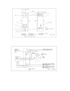
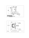
15. Locate and install pitch signal slip ring. Feed the cables through center of shaft
into center weldment. Secure rings using set screws provided. Install slip ring
strain bracket over rings onto pitch gearbox. Secure to gearbox and slip ring
torque arm. See DET-011
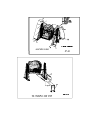
16. Locate and install cabinetry onto all A frames. See DET-012
17. Locate and position control cabinet. DET-006
18. Locate and position Kiosk cabinet. DET-006
19. Locate and install Interface board onto inside left front cabinet wall. See DET-
045
20. Locate and install cockpit power strip to left rear outer cabinet support frame. See
DET-046
21. Locate and install lift center shaft assembly. See DET-047
22. Locate and install Lift motor and drive shaft assemblies. Position and plug motor
and brake power leads into respective power box connections. See DET-048
23. Position and connect respective drive motor cables to power box. See DET-
001,002
24. Connect and install all center weldment cabling secure using tie wraps. Install
Roll motor power and brake connections. See DET-003
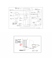
25. Locate the encoders and respective brackets (three). Install brackets on the pitch
and roll motors. Install lift bracket onto later support leg left side. Position
encoder between the bracket legs, push encoder all the way onto the shaft, back
out 1/8” and tighten the encoder set screws (two each encoder). Install respective
cannon plug to the encoder. See DET-004
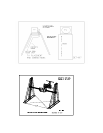
26. Locate and assemble the entry steps. Position in front and under cockpit. See
DET-013
27. Locate and assemble the front support stand. Position per drawing and bolt to the
entry steps. See DET-013