


If the direction of movement is incorrect for any axis, reverse any two (2) phases as described in
paragraph 3-3B above.
2-5 Encoder wiring
The encoders are wired so that the labeled terminals for A and A-not, B and B-not on the encoder are
matched with corresponding terminals on the motion control interface board All cables return and start at
the interface board.
2-5A Encoder Positioning
The pitch and roll encoders are mounted directly to the motor shaft from the rear of the motor so that the
encoder is facing the motor from behind The lift encoder is mounted on the drive shaft connecting the
motor to the ninety degree gear box. Located right inside rear of ride lower level.
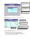
2-5B Encoder Behavior Confirmation
For each axis, the encoder forms a closed loop with the motion control adapter to generate an analog signal
that commands the drive motor to move in a specific direction. In the formula EP=DP-AP, (DP is the
desired position, AP is the actual position and EP is the error position) a positive EP results in a positive
analog signal to move the motor in the direction which will decrease the error.
PITCH: As the unit moves clockwise (up) the encoder reading should return increasing
values (positive). The clockwise Positive registry entry for the axis is set to 1 for true.
ROLL: As the unit moves clockwise the encoder reading should return increasing values
(positive). The clockwise Positive registry entry for the axis is set to 1 for true.
LIFT: As the unit moves up, the encoder reading should return decreasing values to the
registry, where in the software we reverse the appearance of the encoder reading using the
Clockwise Positive registry entry for the axis (set to 0 for false) so that in
the application we
will see increasing values when the unit is going up in inches not degrees..
If the value moves in the opposite direction, check the clockwise positive registry entry
for that axis. If it is set correctly, check the encoder wiring.
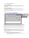
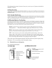
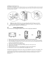
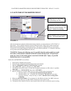
2-6 Mitsubishi Inverter Information
2-6A Appearance and Structure