


5-18 MAINTENANCE WARNINGS and CAUTIONS
5-18A WARNING!
Shock Hazard and Electrocution Hazards exist inside the CPU and around the inside of the
electrical box that houses the inverters.
5-18B CPU
CPU has 115/220 VAC available to the power supply.
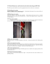
5-18C INVERTERS
There is 208/440/450 VAC available within the power box enclosure. When you want to make OHM
measurements for any reason within this box, remove the input power and allow a wait time of at least
ten minutes to allow the power capacitors within the inverters to drain to zero. These capacitors store
over 400 volts and can cause electrocution, and/or damage test equipment at the least.
NOTE: See the warning above before testing or replacing these units. Also insure that the
replacement inverters are pre-programmed after installation and prior to use.
5-19 Maintenance and testing of Motors
5-19A If you suspect that a motor itself is at fault it can be troubleshot using the power ON and
power OFF OHM test.
a. Ensure power is removed by placing E-Stop to OFF button depressed.
b. Open the wiring junction box on the suspected motor and remove the insulation
wrappings on all lead pairs. Carefully place them so that neither touches each other nor
the frame of the motor.
WARNING! Any motor other than lift that is tested under power ON conditions the unit must be in
the fully raised position or grave damage to equipment or personnel will result by motion of the
platform.
c. If required, RAISE the unit for testing either the Pitch or Roll motors.
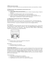
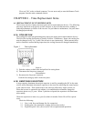
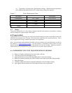
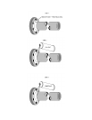
d. Using a voltmeter set to DCV place one lead on L1 the other lead on L2 power lead
coming into the junction box. See drawing attached “Motor Test Procedures”
e. Staying clear of rotation plane of affected axes, have another person activate power by
commanding rotation from the computer console.
f. You should obtain @ 208volts on the meter between phases L1,L2 and/or L3 input leads.
If you do not then the problem is towards the power box. Either rings, wiring or inverter
in power box. Isolate by testing wiring backwards. Use the end to end diagrams provided
in the electrical section end of Chapter 2, to see routing and plug numbers.
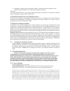
5-19BTesting the motor windings for shorts to ground .
i. Ensure power is removed from the motor and the rest of the motion
platform.
ii. Open the wiring junction box.
iii. Remove all insulation over wiring junctions. List what pair goes to what
color input wire for later reference.
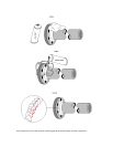
iv. Performing the steps as outlined in drawing “Motor test Procedures”
perform the OHM test of each lead to ground.
v. If you obtain a reading on any lead to ground this is an indication of a faulty
motor. Call Tech services for advice.