


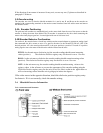
The emergency stop switch, located in the center of the cockpit, activates the emergency stop
condition, returning the machine to its original horizontal (Home) position. The motion platform
can then be lowered to the stairway by using the raise/lower switch.
The upper and lower sensor switches, which are mounted on the center sections of the A-Frames
directly in line with the bearing blocks, signal the computer when the machine is in the proper
position to begin the game (raised) or load and unload passengers prior to or at the end of the
game sequence (lowered).
The electrical swivels allow current and data signals to flow into the cockpit and associated
devices via a series of rotating rings with brushes that make contact and allow pitch and roll
motion through a range of 360 degrees in either direction.
The pitch input connections consist of cockpit power feed (120VAC), grounding wire, left/right
phono jacks, counterweight motor feed, video feed, emergency stop and a data line to the roll
encoder. These signals are then transferred to the center weldment where the power, phono,
video and emergency stop and canopy sensor are transferred to the roll electrical swivel and on to
the cockpit.
Thus, the unit can be described, from an electrical perspective, as being controlled from the
computer and the electrical panel. RS-485 serial communication allows the Mitsubishi inverters
inside the panel to communicate with the computer, thus giving direction to the inverters, and an
analog feedback signal to the CPU, telling the CPU what each inverter is doing. The encoders
also give feedback to the CPU, which is the heart of the system to null out motion and direction.
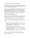
2-2 Motion Platform Axis Movements
In order to insure that the three (3) axis motors (pitch, roll and lift) are moving in the proper
direction, the following observations should be made. Clockwise and counter-clockwise
observations are to be made from the position of the respective motor, facing the cockpit of the
motion platform. For the ROLL axis, the observation point is from the center weldment facing
forward. For the PITCH axis the observation point is from the pitch motor facing the motion
platform. For the LIFT axis the observation point is from behind the motor facing towards the
front of the motion platform.
2-2A Installing the MaxFlight Motion Com Objects (MF Motion)Package Version
1.2.5
Although, the following procedure is normally performed at the factory, there may come
a time when the computer may have to be reloaded from the beginning due to a
malfunction of the drives or other internal components.
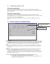
1. Prior to installing the MF Motion package, your system must be updated with the
latest version of Internet Explorer and the latest version of Microsoft Management
Console 1.2.
2. If you are installing on a Windows NT 4.0 system, install Internet Explorer 5.01 and
Microsoft Management Console 1.2. If these versions are already installed, you do
not have to perform these steps. If Windows 2000 system is loaded, the above are
loaded by default.
a. Install Internet Explorer 5.01 or later.
b. Reboot the computer when instructed.