


2-3 Initial Wiring Confidence Check
2-3A Input 3-phase Wiring
The wiring of the individual phases of input power to the controllers does not make any
difference in the behavior of the drive motors. Guarantee that 208/440 or 470 three phase 60 Hz
power is available.
2-3B Output 3-phase Wiring
The wiring of phases between the controller and the motor affects the direction of motor
movement Reverse any two (2) phases of the controllers output to the motor, in order to reverse
the motor direction. Perform paragraph 2-4
To test and set correct drive rotation of all motors. Output power is digital DC to the drive
motors.
2-4 MANUAL CONTROL OF INVERTER DRIVES
WARNING!!
In the following steps all procedures must be followed exactly or grave bodily injury
or equipment damage may occur. Make sure, “E-Stop” is pressed in, power off before proceeding.
If the machine moves in the wrong direction, make corrections as in paragraph 2-3B above.
NOTE: Prior to performing this test, if the inverter/s are run for the first time, Paragraph 2-8 through 2-11
must be complied with or the respective inverter/s will not talk to the computer nor answer commands by
the operator.
WARNING! This test procedure allows the maintenance person direct control of the inverter drive circuits.
There are ”NO SAFEGUARDS” available when these tests are performed. In other words if you
accidentally activate pitch or roll while in the complete down position, you will drive the cockpit and/or
platform into the ground or leveling stands. No one is allowed inside the rotation plane of the platform as
long as this test window is active.
To perform manual inverter drive tests in the following axis these steps must be followed exactly:
1.) Ensure that the “E-Stop” is pressed in, power off to inverters.
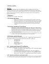
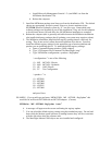
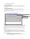
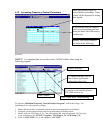
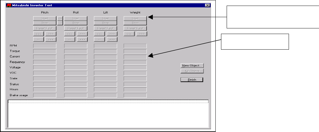
2.) Double click on “Mitsubishi Inverter Test” icon on the desktop or go to program icon. This
opens the test window for all the axes.
This line legend must be
highlighted
Current reading
h